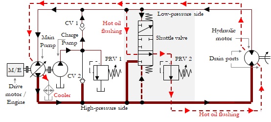
In a closed-circuit hydrostatic transmission (HST) system, a hydraulic pump drives a hydraulic motor. In the closed-circuit HST system, the fluid discharged from the hydraulic motor outlet flows directly to the pump inlet, thus forming a power transmission loop. The transmission loop has a high-pressure side and a low-pressure side. The pressure on the high-pressure side is determined by the load on the motor. A closed-circuit HST system consists mainly of a pump, a motor, a charge pump, check valves, a shuttle valve, pressure relief valves, accumulators, and filters.
A Basic Circuit of the Closed-circuit HST
The basic circuit of a closed-circuit HST with a pump and hydraulic motor is shown in Figure 1. Generally, a variable displacement axial piston pump with a swashplate, whose position can be infinitely varied, is used to drive a fixed-displacement axial piston motor hydraulically. Case drain lines must be provided in the pump and motor for relieving leakage flows.
Figure 1 | Two positions of the basic circuit of a closed-circuit HST
.
.
.
.
A Closed-circuit HST with a Charge Pump, a Flushing Valve, and High-pressure Relief Valves (Alternative Circuit)
As we are aware, the charge pump circuit is used for compensating for the leakage flows and boosting the pressure on the inlet side of the pump. A flushing circuit is used for flushing and lubricating the working parts of the motor and pump cases and increasing cooling and filtering
Figure 2 | An circuit for a closed-circuit HST with an alternative connection of high-pressure relief valves PRV3 and PRV4
As described in the previous section (in the reference book) with a circuit configuration, cross-port high-pressure PRVs are used to limit the maximum operating pressure of the entire system and prevent an inadvertent overload on the hydraulic motor. An alternative circuit for connecting high-pressure relief valves (PRV3 and PRV4) is given in Figure 2. The pressure relief valves are connected back-to-back and are linked to the charge pump circuit, as shown in the figure.
When an over-pressure condition occurs, the flow passes from the high-pressure side to the low-pressure side and back to the inlet side of the main pump. It can be seen that the flow always takes an easier path through a high-pressure relief valve and the check valve that gets opened depending on the pressure conditions in the transmission loop.
HST Sizing
Component
Typical Sizing criteria / Recommendation
Flow rate, charge pump
At least 20% that of the main pump
Total reservoir volume, (in lpm)
Should be between 0.5 to 1.5 times the maximum flow delivered by the charge pump (for closed-circuit applications)
Fluid volume in the reservoir, litre
Should be approximately 80% of the total reservoir volume in lpm
Pressure setting, charge pump PRV
10-35 bar (150 – 500 psi)
Pressure setting, Flushing circuit PRV
Pressure setting, charge PRV minus 2 bar (30 psi)
Pressure setting, High-pressure PRV
20% higher than the main pump compensator setting
Strainer, charge pump suction
Mesh width may be greater than 150 microns
Pressure filter, charge pump
Mesh width of 3 to 10 microns
Pressure filter, mainline
A high-pressure fine filter can be used in the main transmission loop
Heat Exchanger
An HST with a capacity greater than 10 kW is typically provided with a heat exchanger
Reference: Textbook ‘Hydraulic Circuits – Identification of Components and Analysis
Table of Contents– Hydraulic Circuits – Identification of Components and Analysis
Chapter
Description
Page No
—
List of Control Tasks
v
—
Preface
ix
1
An Overview of Hydraulic Systems and Circuits
1
2
Hydraulic Circuits with Directional Control Valves
3
3
Hydraulic Circuits with Check Valves
22
4
Hydraulic Circuits with Flow Control Valves
35
5
Hydraulic Circuits with Flow Dividers and Combiners
56
6
Hydraulic Circuits with Pressure Control Valves
66
7
Hydraulic Circuits with Accumulators
82
8
Circuits for the Series and Parallel Connections of Hydraulic Motors
88
9
Relay-based Electro-hydraulic Circuits
90
10
Circuits for Closed-circuit Hydro-static Transmissions (HSTs)
119
11
Hydraulic Circuits with Variable Displacement Pumps
129
12
Hydraulic Circuits for Load-sensing Systems
135
13
Hydraulic Circuits with Proportional and Servo Valves
140
14
Electro-hydraulic Circuits, Wiring Diagrams, and Ladder Programs of PLC-based Systems
151
15
Hydraulic Circuits with Cartridge Valves
154
16
Hydraulic Circuits with Pressure Intensifiers
169
17
Layouts of Hydraulic Reservoirs
173
18
Application-specific Hydraulic Circuits
180
19
References
197
Book Description
The textbook explores a variety of typical hydraulic circuits in multiple positions and with color graphics. The presentation of the hydraulic circuits is structured with well-thought-out chapters. Each chapter presents circuits from simple to complex levels. Relevant symbols are portrayed chapter-wise for quick understanding. Most of the symbols used are as per ISO 1219. The types of hydraulic circuits include circuits for conventional hydraulics, electro-hydraulics, closed-circuit HSTs, PLC systems, proportional/servo valve systems, and cartridge valve systems.
The book is meant for hydraulic professionals to refresh their circuit ideas and know more about hybrid hydraulic circuits. This book is specially written for professionals who are confused with many types of complex hydraulic circuits. They can systematically learn the critical areas in simple or complex hydraulic circuits. Teachers and students may also make use of this book for enhancing their hydraulic knowledge. The reader can build up a strong foundation for circuit ideas and may apply these ideas to a hydraulic application taking into account the operating and environmental conditions, the orientation of the actuators, the type of materials used, and many supplementary factors.
Available on:
AMAZON – US, UK, DE, FR, ES, IT, NL, PL SE, JP, CA, AU
This article is the second part of the following three-part series of articles:
Filtration and Drying Principles in Pneumatic Systems
Filtration Principles in Hydraulic Systems
Filtration Principles of Pneumatic and Hydraulic Systems: A Comparison Study
A hydraulic power system transmits the power in a controlled manner using an incompressible oil medium. Remember, the fluid medium links all the components in the system and is regarded as a critical element in the system. A fluid is prepared from a base stock and additives. Some examples of base stocks are petroleum oils, high-water-based fluids (HWBF), synthetic fluids, and vegetable oils. And some examples of additives are viscosity index (VI) improver, anti-wear additive, oxidation inhibitor, and corrosion inhibitor. Many types of fluids can be formulated by adding a base stock with varieties of additives to meet the exacting requirements of complex hydraulic systems.
Contamination
Fluids are susceptible to various types of contamination. They are exposed to the following types of contamination: (1) Particulates (dust, dirt, sand, rust, fibres, elastomers, paint chips), (2) Wear metals, silicon, and excessive additives (aluminium, chromium, copper, iron, lead, tin, silicon, sodium, zinc, barium), (3) Water, (4) Sludge, oxidation, and corrosion products, (5) Acids and other chemicals, (6) Sealants (Teflon tape, pastes), and (7) Biological, microbes (in high water-based fluids).
Silt particles (<5 μm) of size corresponding to the typical tolerance in hydraulic components are most dangerous than larger chip particles (>5 μm). Chemical contaminants are formed by the breakdown of additives, due to chemical reactions. The reaction products generate acids and oxidants in the presence of water and heat. They can cause physical and chemical changes in the additive elements. These changes can lead to the deterioration of additives and subsequent fluid breakdown.
Effects of Contamination
Contaminants are the natural enemy of hydraulic components and systems. 70 to 80% of the hydraulic system failures are due to the adverse effects of contaminants, like surface degradation. Even minute particles can damage today’s hydraulic system components due to the existence of minuscule clearances in them. Excessive water contamination is liable to accelerate the ageing process of fluids.
Removal of Contaminants
Particles can be removed by installing correctly sized filters at appropriate locations. The removal of acids, sludge, gums, varnishes, and other oxidation products requires the use of adsorbent filters with active type clay, charcoal, or activated alumina. Magnets can be installed to remove ferrous particles and rust matters. A water-removal filter or a vacuum dehydrator can remove water.
Hydraulic Fluid Cleanliness Standards
Many national and international organizations such as ISO, SAE, National Aerospace Standards (NAS), etc., have developed standards for specifying the particle size classification and contamination concentration levels in hydraulic fluids. The important standards are ISO 4406, NAS 1638, and SAE AS 4059. The cleanliness classes are based on particle sizes, number, and distribution. All standards specify the contamination level in counts per volume and provide easy methods for converting the particle counts into limits that are simple to interpret.
Applicability of the Standards
The ISO 4406: 1999 standard is widely used throughout the world for determining hydraulic fluid cleanliness. The NAS 1638 cleanliness standard was developed for aerospace components in the US in 1964 and is still widely used for industrial and aerospace fluid power applications. It may be noted that NAS 1638 has now been made inactive for new designs. AS4059 class using differential particle count method applies to those currently using NAS 1638 classes and desiring to maintain the methods/format and results equivalent to those specified in the NAS standard. AS4059 class using cumulative particle counts applies to those using the methods of previous revisions of AS4059 and/or cumulative particle counts.
Methods of Particle Counting
ISO 4406 uses the electron microscope counting method. NAS 1638 uses the optical counting method. SAE AS 4059 uses the optical counting method or electron microscope counting method.
Particle Size Classifications
ISO 11171 specifies the following cumulative sizes of particles: >4, >6, and >14 µm.
The NAS 1683 system divides particles into five particle size ranges: 5–15, 15–25, 25–50, 50–100, >100 µm.
SAE AS 4059 specifies the following size ranges of particles for the optical counting method: 6-14, 14-21, 21-38, 38-70, and >70 μm. SAE AS 4059 specifies the following cumulative sizes of particles for the automatic particle counting method: >4 (Code A), >6 (Code B), >14 (Code C), >21 (Code D), >38 (Code E), >70 μm (Code F).
Cleanliness levels
ISO 4406 specifies the cleanliness level of a given sample of fluid by a three-number range code representation, based on the cumulative numbers of particles of sizes greater than 4, 6, and 14 microns respectively, present in one millilitre of the fluid.
NAS 1638 specifies the cleanness level of a given sample of fluid by a single figure (from 0 to 12) representing the maximum allowed differential particle counts (i.e. worst case), present in 100 ml of the fluid, for the designated particle size ranges.
SAE AS 4059 specifies the cleanness level of a given sample of fluid by a single figure representing the maximum allowed cumulative particle counts (i.e. worst case), present in 100 ml of the fluid, for the designated particle sizes according to the particle counting method.
Cleanliness Level Targets
Equipment manufacturers, fluid suppliers, and fluid power associations have established target fluid cleanliness levels applicable for the general types of hydraulic components.
Filters, Hydraulic System
An efficient filtration system should be an integral part of every hydraulic system. Filters remove particulate contamination. When fluid flows through the media, it traps contaminants and at the same time allows the fluid to flow through it easily. A filter mainly consists of the following: (1) Filter Element, (2) Filter bowl, (3) Filter head, (4) Clogging Indicator, and (5) Bypass Valve.
Filter Head
A filter head consists of ports for the inlet and outlet, and visual or electrical indicators. It is made of cast Aluminium as a standard material or ductile iron for high-pressure applications.
Filter Housing
A filter housing encloses the filter element. Housing styles are categorised as: removable housing/cartridge unit, spin-on, in-tank, and in-line. It is usually made of ductile iron or stainless steel.
Filter Element
A filter element is usually made of steel wire screen, cellulose media, or synthetic glass fibre media. It consists of millions of tiny pores of micron sizes. A piece of filter media is pleated and assembled in a canister as disposable elements.
Steel Wire Media
Wire-mesh media are made of epoxy-coated stainless steel. The filter captures contaminants in a fluid stream on one side of the wire screen, which faces the fluid flow (surface filtration). This type of filter element is used to make coarse filters, usually known as strainers. Typically wire-mesh filters are used to catch very large, harsh particulate matter that could rip up a normal filter. Wire-mesh media are available in 3 mesh sizes: (1) 100 mesh yields 150 µm filtration, (2) 200 mesh yields 74 µm filtration, and (3) 325 mesh yields 44 µm filtration.
Cellulose Media
Cellulose Media are made from plant fibres and are held together by resins. The pores are microscopic. The thick-walled media absorbs contaminants throughout the depth of the material as the fluid flows through the media (depth media).
Glass Fibre Synthetic Media
Synthetic Media are man-made, consistent, and rounded off to provide the least flow resistance. They are made of inorganic micro-fine glass fibres. They are randomly laid into a multi-layered web with tapered pore geometry (larger pores on the upstream surface and finer and finer pores towards the downstream side). The thick-walled glass fibre media captures contaminants throughout the depth of the media.
By-pass Valve Setting
Bypass valves have cracking pressures typically in the range between 0.1 bar (2 psid) and 7 bar (100 psid). Suction and return-line filters have a lower setting [max. 1 bar (14.5 psid)] than that of the pressure-line filters [max. 7 bar (100 psid)].
Service Indicators
The filter can be provided with a pressure gauge, visual indicator, and/or electrical indicator to point out the need for the replacement of its filter element.
Magnet
A magnet can be incorporated to attract and hold ferromagnetic particles down to even smaller than 1 micron.
Installation Locations, Filters
Based on the installation locations, hydraulic filters can be classified as: (1) Strainers, (2) Suction filters, (3) Pressure filters, (4) Return-line filters, and (5) Offline filters.
Strainer
It is installed at the pump suction side. It is a coarse filter, made of a piece of wire mesh, typically having a mesh width of ≥149 μ.
Suction filter
The suction filter is connected to the pump suction side. It is a coarse filter typically having a mesh width in the range from 5 to 149 μ. It is usually mounted outside of the reservoir in a service-friendly manner. It protects the pump from coarse particles, economically.
Pressure filter
It is installed downstream of the pump. It can also be smaller and finer (10 – 20 μ). The main function is to keep the fluid that comes directly from the pump clean. It serves to protect expensive and dirt-sensitive downstream components.
Return-line filter
It is installed in the return-line. The purpose is to trap dirt from the system working components, as well as particles entering the system through the worn piston-rod seals in the system.
Off-line filtration
It consists of a separate pump, filter unit, hoses, and quick-disconnect couplers. The components can be arranged on a mobile cart and retrofitted to an existing system temporarily or integrated into the hydraulic system permanently. In this system, fluid is pumped out of the reservoir, passed through the filter, and allowed to return to the reservoir continuously.
Air Breather
Air breathers provide fast-acting protection against airborne moisture and particulate contamination. They stop solid particulate down to 3 µm at 97% efficiency and prevent moisture from entering the reservoir.
37 books in Paperback and Kindle eBook versions on the subjects of Pneumatics and Hydraulics, authored by Joji Parambath, have been published under Fluid Power Educational Series. Joji Parambath is a trainer in the field of Pneumatics, Hydraulics, and PLC, for over 25 years. All the books are available at Amazon marketplaces.
These textbooks deal with the components and circuits of hydraulic systems. The fundamentals required to understand the core topics are given initially. The book describes the topics on hydraulic fluids, filters, power packs (reservoirs, pumps, pressure relief valves) hydraulic actuators, directional control valves, flow control valves, pressure control valves, fluid conductors, and accumulators, in detail. Further, the book presents the maintenance, troubleshooting, and safety aspects of hydraulic systems.
These books separately describe the design aspects of hydraulic systems in the SI system units and the English system units for educational purpose. These books highlight the essential parameters, mathematical relations, and specifications of many hydraulic components such as hydraulic pumps, reservoirs, pressure relief valves, filters, fluids, hydraulic cylinders, hydraulic motors, control valves, accumulators, and fluid conductors. Examples of designing typical industrial hydraulic systems are also given in this book. Patient learners can extract many design concepts from any of these invaluable books.
The book on hydraulic fluids explains, in detail, the functions, types, characteristics, and selection of hydraulic fluids. The subsequent sections present topics on fluid contamination, the effect of contamination on fluids, fluid analysis, fluid quality standards, and the maintenance aspects of fluids.
This book on filters presents the principles of filtration in hydraulic systems. These principles include the materials of filter media, various designs of filters, and the typical locations of filters in hydraulic systems. Further, this book describes the filter element performance ratings, such as the micron ratings, beta ratio, and filter efficiency, and the multi-pass test to determine such ratings.
These books take up a detailed discussion of hydraulic power packs and their constituent parts including reservoirs, pumps and pressure relief valves. These books also give a brief note on the topic of heat dissipation and sound reduction techniques in hydraulic systems.
These books bring out the essential technical information related to hydraulic cylinders, in a simple and easy to understand manner. The topics include the principal parts and body styles, position transducers, piston-rod buckling, classification and types, side loads, installation and mounting, advantages, applications, standards, maintenance and safety, and design of hydraulic cylinders.
These books bring out the fundamentals and other most essential technical information related to hydraulic motors. The topics include basic hydraulic motor working, terms and definitions, constructional features, side loads, classification, comparison, performance characteristics, applications, and maintenance of hydraulic motors.
These books bring out the essential technical information related to hydraulic accumulators extracted, especially from the material available from the manufacturer’s domain. The topics include functions, classification, constructional features, comparison, pre-charging, safety requirements, applications, maintenance, and accumulator sizing. Many hydraulic circuits with accumulators are also presented.
These books present information about the constructional features, performance specifications of pipes, tubes, and hoses and their fittings. The topics include the terms & definitions and design of hydraulic conductor systems, and installation, routing, and maintenance of fluid conductors.