In a closed-circuit hydrostatic transmission (HST) system, a hydraulic pump drives a hydraulic motor. In the closed-circuit HST system, the fluid discharged from the hydraulic motor outlet flows directly to the pump inlet, thus forming a power transmission loop. The transmission loop has a high-pressure side and a low-pressure side. The pressure on the high-pressure side is determined by the load on the motor. A closed-circuit HST system consists mainly of a pump, a motor, a charge pump, check valves, a shuttle valve, pressure relief valves, accumulators, and filters.
A Basic Circuit of the Closed-circuit HST
The basic circuit of a closed-circuit HST with a pump and hydraulic motor is shown in Figure 1. Generally, a variable displacement axial piston pump with a swashplate, whose position can be infinitely varied, is used to drive a fixed-displacement axial piston motor hydraulically. Case drain lines must be provided in the pump and motor for relieving leakage flows.

Figure 1 | Two positions of the basic circuit of a closed-circuit HST
.
.
.
.
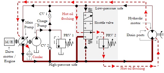
A Closed-circuit HST with a Charge Pump, a Flushing Valve, and High-pressure Relief Valves (Alternative Circuit)
As we are aware, the charge pump circuit is used for compensating for the leakage flows and boosting the pressure on the inlet side of the pump. A flushing circuit is used for flushing and lubricating the working parts of the motor and pump cases and increasing cooling and filtering

Figure 2 | An circuit for a closed-circuit HST with an alternative connection of high-pressure relief valves PRV3 and PRV4
As described in the previous section (in the reference book) with a circuit configuration, cross-port high-pressure PRVs are used to limit the maximum operating pressure of the entire system and prevent an inadvertent overload on the hydraulic motor. An alternative circuit for connecting high-pressure relief valves (PRV3 and PRV4) is given in Figure 2. The pressure relief valves are connected back-to-back and are linked to the charge pump circuit, as shown in the figure.
When an over-pressure condition occurs, the flow passes from the high-pressure side to the low-pressure side and back to the inlet side of the main pump. It can be seen that the flow always takes an easier path through a high-pressure relief valve and the check valve that gets opened depending on the pressure conditions in the transmission loop.
HST Sizing
| Component | Typical Sizing criteria / Recommendation |
| Flow rate, charge pump | At least 20% that of the main pump |
| Total reservoir volume, (in lpm) | Should be between 0.5 to 1.5 times the maximum flow delivered by the charge pump (for closed-circuit applications) |
| Fluid volume in the reservoir, litre | Should be approximately 80% of the total reservoir volume in lpm |
| Pressure setting, charge pump PRV | 10-35 bar (150 – 500 psi) |
| Pressure setting, Flushing circuit PRV | Pressure setting, charge PRV minus 2 bar (30 psi) |
| Pressure setting, High-pressure PRV | 20% higher than the main pump compensator setting |
| Strainer, charge pump suction | Mesh width may be greater than 150 microns |
| Pressure filter, charge pump | Mesh width of 3 to 10 microns |
| Pressure filter, mainline | A high-pressure fine filter can be used in the main transmission loop |
| Heat Exchanger | An HST with a capacity greater than 10 kW is typically provided with a heat exchanger |
By
Joji Parambath
Author (Amazon Author Page)
Reference: Textbook ‘Hydraulic Circuits – Identification of Components and Analysis

Table of Contents – Hydraulic Circuits – Identification of Components and Analysis
| Chapter | Description | Page No |
| — | List of Control Tasks | v |
| — | Preface | ix |
| 1 | An Overview of Hydraulic Systems and Circuits | 1 |
| 2 | Hydraulic Circuits with Directional Control Valves | 3 |
| 3 | Hydraulic Circuits with Check Valves | 22 |
| 4 | Hydraulic Circuits with Flow Control Valves | 35 |
| 5 | Hydraulic Circuits with Flow Dividers and Combiners | 56 |
| 6 | Hydraulic Circuits with Pressure Control Valves | 66 |
| 7 | Hydraulic Circuits with Accumulators | 82 |
| 8 | Circuits for the Series and Parallel Connections of Hydraulic Motors | 88 |
| 9 | Relay-based Electro-hydraulic Circuits | 90 |
| 10 | Circuits for Closed-circuit Hydro-static Transmissions (HSTs) | 119 |
| 11 | Hydraulic Circuits with Variable Displacement Pumps | 129 |
| 12 | Hydraulic Circuits for Load-sensing Systems | 135 |
| 13 | Hydraulic Circuits with Proportional and Servo Valves | 140 |
| 14 | Electro-hydraulic Circuits, Wiring Diagrams, and Ladder Programs of PLC-based Systems | 151 |
| 15 | Hydraulic Circuits with Cartridge Valves | 154 |
| 16 | Hydraulic Circuits with Pressure Intensifiers | 169 |
| 17 | Layouts of Hydraulic Reservoirs | 173 |
| 18 | Application-specific Hydraulic Circuits | 180 |
| 19 | References | 197 |
Book Description
The textbook explores a variety of typical hydraulic circuits in multiple positions and with color graphics. The presentation of the hydraulic circuits is structured with well-thought-out chapters. Each chapter presents circuits from simple to complex levels. Relevant symbols are portrayed chapter-wise for quick understanding. Most of the symbols used are as per ISO 1219. The types of hydraulic circuits include circuits for conventional hydraulics, electro-hydraulics, closed-circuit HSTs, PLC systems, proportional/servo valve systems, and cartridge valve systems.
The book is meant for hydraulic professionals to refresh their circuit ideas and know more about hybrid hydraulic circuits. This book is specially written for professionals who are confused with many types of complex hydraulic circuits. They can systematically learn the critical areas in simple or complex hydraulic circuits. Teachers and students may also make use of this book for enhancing their hydraulic knowledge. The reader can build up a strong foundation for circuit ideas and may apply these ideas to a hydraulic application taking into account the operating and environmental conditions, the orientation of the actuators, the type of materials used, and many supplementary factors.
Available on:
AMAZON – US, UK, DE, FR, ES, IT, NL, PL SE, JP, CA, AU
Are you looking for a course on Pneumatics and Hydraulics?
Please visit Fluidsys Training Centre Pvt. Ltd., Bangalore, India. https://fluidsys.in


