The preventive maintenance is carried out on hydraulic systems to keep them in a perfect working condition at all times. However, faults or breakdowns do occur in hydraulic systems, which have to be traced and corrected with minimum delay and expense. Table below gives pump malfunctions and their potential causes and rectification.
Disturbances
Possible causes
Rectification
Loud pump noise
Cavitation
-Clean dirty strainer/filters -Replace defective filters -Use filter of correct size -Change system fluid -Maintain fluid level in reservoir -Warm up fluid, if too cold -Clean reservoir breather vent -Correct drive motor speed
Hot pump
Hot fluid
-Increase reservoir capacity -Change system fluid -Change filters -Clean/replace cooler
Low pump discharge
Low flow
-Replace with correct type -Set valve correctly -Replace or overhaul -Tighten leaking connections -Adjust swash plate angle correctly
Pump slows down or stalls
Low voltage supply
-Provide correct power supply
Pump slows down or stalls
Drive motor in Star connection
-Re-wire in Delta connection
Motor turns backwards
Phase reversal
Interchange any two phases
Motor erratic/ not operating
Wrong motor wiring,
-Re-configure wiring
Motor erratic/ not operating
Wrong power supply
-Provide correct power supply
References:
Categories of malfunctions in hydraulic systems in terms of its general disturbances, and their possible causes and rectification are presented in the above books. Further, the component-wise malfunctions and their potential causes and rectification are also presented.
Joji Parambath
Director
Fluidsys Training Centre
Are you looking for a course on Pneumatics and Hydraulics?
Please visit Fluidsys Training Centre Pvt. Ltd., Bangalore, India. https://fluidsys.in
Any hydraulic system is inherently dangerous, as an enormous amount of energy is transmitted through the high-pressure system. There are many hazards associated with hydraulic systems. The safety of personnel must be ensured while they are operating and maintaining hydraulic systems. Every operator of hydraulic systems has the right to know the hazards of his/her occupation.
The pressurized fluid in a hydraulic system may get discharged when a component fails. This discharge can cause the dangerous release of mechanical forces unexpectedly. Components or fittings can eject or move unexpectedly, hoses can whip around with great force, or high-pressure fluid can inject through pinholes at a very high speed. When maintenance is to be carried out on a system with accumulators, it is essential to isolate the power source from the rest of the system, open the bleed valve, and verify the system pressure.
References:
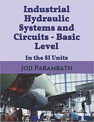
Industrial Hydraulic Systems and Circuits – Basic Level in the SI Units
Joji Parambath
Industrial Hydraulics – Basic Level in the English Units
Joji Parambath
Hydraulic systems, including fluid and components, are very hot. Certain fluids can chemically burn the skin. The exposure of the hot fluid to the skin can cause the blistering of the skin and even burns. Some types of hydraulic fluids are also flammable. Elevated temperatures may cause the release of toxic vapours from fluids, which are harmful when inhaled. Some people can get allergies when exposed to hydraulic fluids or the additives within the fluids. Eyes are more sensitive to fluid splash than other parts of the body. Therefore, it is essential to use Personnel Protective Equipment (PPE) when working with hydraulic systems.
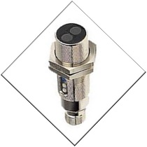
Discrete output proximity sensors are most important for industrial applications. They gain importance in such applications where it is necessary to record or count moving objects or work-pieces on machines or conveyors. Based on the way of connection of the final output amplifier transistor of a discrete proximity sensor to the power supply terminals, proximity sensors can be categorized into two types:
Sinking (NPN) output sensors
Sourcing (PNP) output sensors
Sourcing (PNP) Output sensor
The sourcing output sensor has a PNP transistor output with its emitter connected to the +Vcc of the supply for positive switching, as shown in Figure 1. The load is connected between the proximity sensor output and the negative potential. This connection means that the sensor output will be pulled up to the positive potential, and hence the grounded load will be connected to the positive potential through the transistor in the switched state. This connection will allow the current to flow from the positive potential through the sensor to the output (hence sourcing). This sensor is best selected when all electrical devices in the control system use a single source of the supply voltage.
Figure 1 | A sourcing output proximity sensor and its load connection
Discrete Sensor connection to PLC Input
As discussed, the output of a discrete proximity sensor can be sinking or sourcing type. Similarly, a discrete PLC input can be sinking or sourcing type. Remember, it is important to interface a proximity sensor to the associated PLC input correctly for the proper operation of the PLC system. In general, a sourcing proximity sensor should be connected to a sinking PLC input, and a sinking proximity sensor should be connected to a sourcing PLC input to avoid the erratic operation of the system. For the sourcing sensor output, the PLC input circuit is wired with the common terminal connected to the common of the sensor, as shown in Figure 2.
Figure 2 | A sourcing sensor output connected to a sinking PLC input
Electro-pneumatics and Automation
Joji Parambath
This book explains the functioning of primary solenoid valves and various electrical control components. Many typical single-actuator and multiple-actuator electro-pneumatic circuits are also developed to illustrate various applications of electro-pneumatics.
As you are aware, a pneumatic system is an interconnection of various components such a compressor, actuators, control valves, and other elements using fluid conductors. The operation of the pneumatic system is affected by the presence of heat, dust, moisture, leaks, loose bolts, and misalignment in the system. Lack of regular maintenance may result in the premature wear of moving parts, the loss of air and associated pressure drops, and increased downtime of pneumatic components. Therefore, a good preventive maintenance program must be in place for removing the harmful elements from the system from time to time, and usually as per a checklist. In general, maintenance includes the following closely-related activities: (1) Visual inspection, (2) Servicing, (3) Examination, and (4) Overhaul.
Requirements for Preventive Maintenance
The most general requirements of preventive maintenance are as follows: (1) Know the machine, (2) Understand and follow the best maintenance practices, (3) Compile a maintenance checklist, (4) Follow instruction manual, (5) Ensure safety, and (6) Stock spares.
Concern for Safety
The safety of personnel and equipment should always be kept in mind while carrying out routine maintenance activities. Safety can be built into a pneumatic system by incorporating interlocks, power-failure locks, and an emergency shutdown feature. Though the responsibility of building safety into a machine rests with the manufacturer of the machine, every technician should observe and practice relevant safety regulations. Further, every maintenance technician should make a serious attempt to know the hazards involved in his/her occupation.
Activities for Good Maintenance during the Design Phase
The planning for the good maintenance of a pneumatic system begins right from the design stage of the system. That means, the design must facilitate easy maintenance and the efficient removal of contaminants. Further, it is better to plan and design a pneumatic system with correctly-sized and inherently-safe components for its reliability and long service life.
Activities for Good Maintenance during Installation
Additionally, it is required to install a machine in such a way that there is ample space for the operation and maintenance of the machine. It is also essential to provide adequate lighting and a clean environment. The service indicators must be easily visible, and service points must be accessible without any difficulty.
Maintenance, Troubleshooting and Safety in Pneumatic Systems
Joji Parambath
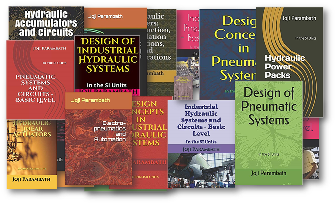
Details of many other books under Fluid Power Educational Series from the same author can be accessed from:
It is essential to maintain various conditioning devices, like coolers, filters, dryers, and lubricators, at regular intervals, for the removal of heat and other harmful contaminants. The routine maintenance activities generally include cleaning, visual inspection, running checks, and servicing of filters, lubricators, and coolers. The reason for any abnormal noises in the system should be investigated immediately.
Plugging Leaks
An essential requirement of any pneumatic system is to stop leakage, as expensive leaks cost big money. Application of soapy water or commercially available leak detecting liquids, like aerosol sprays, on suspected joints, might reveal the presence of leaks. An ultrasonic leak detection instrument can also be used to locate leakages.
Mounting of Components / Machines
The mounting bolts of components must be torqued correctly. Further, every prime mover must be perfectly aligned with the associated load part to reduce undue stress on components, seals, and bearings. A maintenance technician should check for any vibration, loose bolts, or misalignment of components in a system.
Seals (or packings) are deformable materials sandwiched between the mating surfaces to close of their small gaps. They retain fluid under pressure within the system and keep foreign matter out. They prevent the metal-to-metal contact of sliding surfaces. They are made from polymer materials that are flexible (rubber) and soft (plastics). The elastomeric quality enables them to flex more efficiently.
Polymerization
A single molecule consisting of a group of similar or dissimilar atoms is known as ‘mer’ or ‘monomer. When conditions are right, several monomers can link together chemically to form long, chain-like structures (polymerization process). The resulting macromolecules incorporating thousands of monomers are known as polymers. Polyethylene, rubber, plastics are examples of polymer-based materials. According to the way the molecules are arranged in polymers, they can be of amorphous or crystalline type.
Amorphous Polymers
Amorphous polymers are composed of long and twisted molecular chains that are non-symmetrical. The intermolecular forces are weak in amorphous polymers. All rubbers (elastomers) are amorphous at room temperature. When a compressive load/stretching force is applied to the elastomeric material, the entangled molecular chains uncoil and straighten them. When the stress is removed, the chains tend to coil up again, reverting to their normal state of entanglement.
Crystalline Polymers
Crystalline polymers are composed of orderly arranged molecules. The intermolecular forces are strong in crystalline polymers. The orderly arranged molecules of polymers are rigid. Most plastics are either crystalline or semi-crystalline.
Polymer Additives
Seals are liable to encounter potentially harmful service and environmental conditions such as extreme pressure and heat/cold. Other ingredients must be added to enhance its physical and chemical properties. These ingredients may include fillers (to reinforce the material), cure activators and accelerators (to increase cure speed), plasticizers (to aid flexibility), and pigments (for colourization).
Properties of Polymers
The number of molecules (the chain length) and thus the molecular weight has a significant impact on the polymer’s physical properties. That is, polymers with high molecular weights are essential in the formulation of tough materials meant for applications with severe operating conditions. Physical Properties of polymers include hardness, tensile strength, tear resistance, abrasion resistance, compression set, and resilience. When the polymer is heated, its inter-molecular forces decrease. The seal material must be chemically compatible with the system fluid.
Amazing Book Series!! For more Hydraulic Knowledge, Please Read the Fluid Power Educational Series Books
Hardness is measured with a portable instrument called ‘Shore durometer’. It utilizes a cone indenter point loaded by a calibrated spring to gauge the resistance of the test specimen of seal material to indentation. The penetration depth (d) of the indenter under the load determines the hardness of the specimen. There are two Shore scales used for measuring the hardness.
Shore A Scale
The Shore A scale is used for testing soft elastomers (rubbers). Its loading force is 822 g, and it uses a lighter spring and a 350 angle indenter point.
Shore D Scale
The Shore D scale is used for testing hard elastomers (plastics). Its loading force is 4536 g, and it uses a stiffer spring and a sharp 30° angle indenter point.
Measurement Procedure
When the Shore A durometer is pressed against a flat elastomer, the indenter point is forced back against the spring. The force reflects on the gauge with an arbitrary scale of 0 to 100. Harder substances generate large durometer numbers. The most common hardness range for seal materials for hydraulic systems is from 50 to 80 Shore A. The shore D durometer accurately measures the hardness of materials that are harder than 90 Shore A.
Terms and Definitions
Compression set is the amount by which the seal material remains short of its original shape after being released by the compressive load. This parameter is, usually, expressed as a percentage of its original dimension. A seal often hardens and assumes the gland shape due to compression set.
Extrusion refers to the flow of a part of an O-ring into the clearance between two mating metal parts when subjected to high pressure. The extruded portion of the seal is liable to be nibbled away from the low-pressure side. The continuous biting away of the extruded part can lead to a complete seal failure. Anti-extrusion devices can be used to avoid extrusion.
Factors Affecting Seal Performance
System and device parameters that affect the seal performance are the pressure, temperature, the speed of movement of dynamic sealing surfaces, the quality and finish of mating surfaces, and the humidity. The properties of the seals are also affected by their exposure to oxygen, ozone, and sunlight.
Pressure
Seals are subjected to operating pressures as well as the shock pressures. Further, excessive pressure can cause seal extrusion and pressure spikes can deform the seals. The result of repeated deformations is the premature wear of the seal materials.
Temperature
Lower temperatures may harden the seals and make them brittle. At higher temperatures, the seal materials may become too soft to withstand the applied pressure and are susceptible to extrusion.
Speed
As the speed of a moving part at the contact surface of a seal increases, the fluid film between the sealing surfaces breaks and, as a result, more friction is produced.
Surface finish
Improperly finished metal surfaces generate greater friction. Smooth surfaces lack the necessary cavities to hold the lubricating fluids. The purpose of all surface finishes is to provide surfaces that inflict least wear to seals. The range of ideal average roughness (Ra) of the working surfaces in hydraulic systems is 0.5 to 0.6 μm.
Oxygen, Ozone & Sunlight
Oxygen, especially along with heat, causes the hardening of the seal. Ozone and sunlight are capable of causing breakage of the polymer chains.
Classification of Hydraulic Seals
A static seal is used in between stationary parts in hydraulic devices to seal high-pressure fluid. A dynamic seal is used in-between parts, where there is reciprocating or rotary motion. In reciprocating seal applications, a seal slides back and forth within its gland. In rotary seal applications, a seal moves radially within its groove.
Static Seals
O-ring is probably the most commonly used static seal. In high-pressure systems, static seals may be configured with backup rings to prevent excessive compression of the seals and seal extrusion.
Dynamic Seals
Hydraulic seals for applications involving the oscillation or slow rotation with surface speeds less than 15 metres/min are usually classified as dynamic seals. Hydraulic seals for applications involving high-speed rotation with surface speeds greater than 15 metres/min (0.8 ft/s) are usually classified as high-speed rotary seals.
Seal Materials
Elastomer Group
Acrylonitrile/Butadiene (NBR)
Based on butadiene and acrylonitrile copolymer
Excellent abrasion resistance, high tensile strength, and high resilience
Good compatibility with petroleum-based fluids
Limited resistance to heat
Most widely used for U-cups, Lip seal, and V-packing
Viton (Fluorocarbon Rubber or FKM)
Carbon backboned polymers, highly fluorinated
Excellent heat resistance, with thermal stability up to 262 0C
Compatible with a broad range of fluids
Low compression set and excellent ageing characteristics
Used for U-cup seals, lip seals, V-packing, and wipers
Silicon Rubber
Made from silicon, oxygen, and carbon
Offers good resistance to compression set, at high temperatures
Highly resistant to sunlight, ozone, oxygen, and moisture
Mainly used as static seals
Used for O-rings, gaskets, and special seals
Ethylene Propylene Rubber (EPR)
Offers excellent resistance to heat, ozone, and UV light
Not suitable for petroleum-based fluids
Used for ester-based fluids, such as Skydrol
Used for U-cup seals, lip seals, and V-packing
Plastic Group
Polyurethane
Formulated from copolymers of ether- or ester-based urethanes
An excellent choice for petroleum-based fluids
Good mechanical properties, such as high resilience and high tensile strength
Good resistance to extrusion, abrasion, tear, oxidation, and oil swell
Maintains the stability of shapes of sealing edges
Provides long service life
Nylon
Formulated from synthetic rubber and fluorine
Very high heat resistance and excellent mechanical properties
Low water absorption and good chemical resistance
Good low-temperature properties and creep resistance
Used for backup rings, anti-extrusion rings, guide ring bushes, and scrapers
P T F E (Teflon) Group
PTFE (polytetrafluoroethylene)-Teflon -is a fluoro-plastic distinguished by excellent resistance to chemicals
Virgin PTFE
Offers excellent resistance to most chemicals
Very low coefficient of friction
Operates over a broad range of temperatures
Tendency to creep, depending on the temperature and load
Used for backup rings, V-packing, O-rings, rotary seals, and gaskets
15% Glass-filled/60% Bronze-filled PTFE
A virgin PTFE is fortified with glass fibre and/or bronze to retain their toughness and flexibility, reduce their thermal expansion, and, improve their wear strength
Excellent chemical inertness and high heat resistance
Low-temperature flexibility and low running friction
Higher resistance to extrusion as compared to virgin PTFE
Preferred for high power hydraulic applications
Used for making piston seals, rod seals, and wipers
An electro-pneumatic system, in general, consists of an electrical or electronic control part controlling the pneumatic power part of the system. Integrating the power density of pneumatic systems with the controlling possibilities of the electric systems opens up a new world of opportunities for the high-performing pneumatic systems. In this hybrid technology, solenoid valves are used as interfaces between the control part and the power part. A conventional solenoid valve acts as a converter that generates pneumatic outputs in response to electrical input signals. Control and feedback elements like pushbuttons (PBs), relays, sensors, and timers are used in the electro-pneumatic systems for obtaining the desired control.
A well-written book entitled ‘Electro-pneumatics and Automation’ authored by Joji Parambath in the paperback and Kindle versions are available for the study of electro-pneumatics and automation. I am hopeful that a high level of competence in developing electro-pneumatic circuits can be achieved with the help of the book.
This book explains the functioning of solenoid valves and various electrical control components such as relays, pushbuttons, limit switches, proximity sensors, timers, counters, pressure switches. Many typical single-actuator and multiple-actuator electro-pneumatic circuits are also developed to illustrate various applications of electro-pneumatics. The development of electro-pneumatic circuits is explained systematically with progression from simple to complex levels. Some typical circuits which are well-covered in the book are briefly indicated here.
Control of a Double-acting Cylinder Using an Electronic Timer
A double-acting cylinder is to extend when a pushbutton is pressed (short pulse). It is to remain in the extended position for 5 seconds and then to return automatically. The final forward position of the cylinder is registered with a proximity sensor S2. A 5/2-DC double-solenoid valve is used as the final control element. Develop an electro-pneumatic control circuit to implement the control task.
Design for a two-group Electro-pneumatic Multiple-actuator Circuit
In the development of a simple two-group electro-pneumatic circuit, it is necessary to divide the power supply into two groups in such a way that at any point of time, only one group is live with the other group switched off. A two-group circuit can efficiently be designed using a single relay. The structure of a group-changing cascade circuit for two groups (say G1 and G2) using a relay is given in the Figure below.
Control of a Pneumatically-controlled drilling machine
Work-pieces are to be drilled using a pneumatically-controlled drilling machine given in Figure 4.10. The work-pieces are arranged in a gravity feed magazine. The work-pieces are pushed and clamped using a clamping cylinder A, drilled by a drilling cylinder B, and ejected by an ejecting cylinder C. Develop an electro-pneumatic control circuit to implement the control task as given in the associated displacement-step diagram.
The cleanliness of hydraulic fluids needs to be monitored for maintaining the components of hydraulic systems at a satisfactory level. Many national and international organizations such as ISO, SAE, National Aerospace Standards (NAS), etc., have developed standards for specifying the particle size classification and contamination concentration levels in hydraulic fluids. All standards specify the contamination level in counts per fluid volume and provide easy methods for converting the particle counts into limits that are simple to interpret. Here is an overview of these standards.
The cleanliness classes are based on particle size [differential (e.g. 5 – 15 µm) or cumulative (e.g.>6 µm)], number, and distribution. Before proceeding further, the knowledge of the following terms and definitions would be of great help in understanding various cleanliness standards.
Methods of particle counting
There are two basic methods of counting particles in hydraulic fluids.
By using an optical microscope where the longest dimension sizes the particles. [See Figure 1(a)]
By using automatic particle counters (APCs) calibrated as per ISO 11171, where the particles are sized by the area rather than the length. [See Figure 1(b)]
Figure 1 | Sizing of particles
Particle size analysis
Several methods and instruments, based on different physical principles, are used to determine the size distribution of the particles suspended in a given sample of hydraulic fluid. The numbers of particles found in the different size ranges characterize this distribution. A particle to be analyzed can be sized by: (1) the longest dimension, as sized by a microscope, or (2) the equivalent projected area, as sized by APC calibrated as per ISO 11171.
The ISO System
In ISO 4406: 1999, particle counts are determined cumulatively, for particle sizes > 4 μm(c), > 6 μm(c), and > 14 μm(c) as per the size classification standard ISO 11171, using particle counters and allocated to measurement codes. In 1999, the previous version of the standard, i.e., ISO 4406:1987, was revised and the size ranges of the particle sizes redefined. The contamination code rating system as per ISO 4406: 1999 is given in Table 1.
The NAS System
The NAS 1638 was originally developed in 1964 to define classes for the contamination present within aircraft components. The application of this standard was extended to industrial hydraulic systems as no other standards existed at the time.
In the NAS 1638 classification, the code number refers to a maximum quantity of particles within a specific size class. The NAS system divides particles into five particle size ranges. A series of 14 classes were specified, covering very clean to very dirty levels. The method of counting the particles referenced the optical microscope method. The NAS code specifies a single code number based on the highest particle count in any of the size ranges. As the code number goes high, the degree of contamination increases for any size range. This standard is now considered obsolete. However, it is still widely used in old systems. The cleanliness codes as per NAS 1638 is given in Table 4.
The SAE System
The SAE aerospace standard AS4059 was developed in 1988 as a replacement/equivalent to the obsolete NAS 1638 format. Since then this standard has undergone six revisions and is now at issue ‘F’. This standard specifies contamination classes and levels of particulate contamination in hydraulic fluids. This standard offers two classifications. One classification, based on the microscopic counting, applies to those currently using NAS 1638 classes and desiring to maintain the methods/format. The other alternative, based on the automatic particle counting, applies to those using the methods of previous revisions of AS4059 and/or cumulative particle counts. The cleanliness classes for differential particle counts are given in Table 2, and the cleanliness classes for cumulative particle counts are given in Table 3.
Meaning of Index (c)
Particle size specifications usually contain the index(c), [Example: 4 μm(c)]. This notation is used to indicate that the calibration material used is certified and traceable to a national standard.
A Comparative Study
A comparative study of these standards in terms of the methods of particle counting, particle size classification, contamination concentration levels, and the applicability of these standards is undertaken in the following sections.
Method of Particle Counting
ISO 4406: 1999 uses the electron microscope counting method
SAE AS 4059 Rev F uses the optical counting method or electron microscope counting method
NAS 1638 uses the optical counting method
Particle Size Classification
ISO 11171 specifies the following three-dimensional cumulative sizes of particles:
>4 µm(c)
>6 µm(c)
>14 µm(c)
SAE AS 4059 specifies the following size ranges of particles for the optical counting method:
6 -14 μm(c)
14 -21 μm(c)
21 -38 μm(c)
38 -70 μm(c)
>70 μm(c)
SAE AS 4059 specifies the following cumulative sizes of particles for the automatic particle counting method:
> 4 μm(c) (Code A)
> 6 μm(c) (Code B)
> 14 μm(c) (Code C)
> 21 μm(c) (Code D)
> 38 μm(c) (Code E)
> 70 μm(c) (Code F)
NAS 1638 specifies the following differential sizes of particles:
5 – 15 µm
15 – 25 µm
25 – 50 µm
50 – 100 µm
> 100 µm
Contamination Concentration Levels
In ISO 4406: 1999 specifies the cleanness level of a given sample of fluid by a three-number range code representation, based on the cumulative numbers of particles of sizes greater than 4, 6, and 14 microns respectively, present in one millilitre of the fluid.
SAE AS 4059 specifies the cleanness level of a given sample of fluid by a single figure representing the maximum allowed cumulative particle counts (i.e. worst case), present in 100 ml of the fluid, for the designated particle sizes according to the particle counting method.
NAS 1638 specifies the cleanness level of a given sample of fluid by a single figure (from 0 to 12) representing the maximum allowed differential particle counts (i.e. worst case), present in 100 ml of the fluid, for the designated particle size ranges.
Applicability of the Standards
In ISO 4406: 1999 standard is widely used throughout the world for determining the hydraulic fluid cleanliness.
AS4059 class using differential particle count method applies to those currently using NAS 1638 classes and desiring to maintain the methods/format, and results equivalent to those specified in NAS 1638.
AS4059 class using cumulative particle counts applies to those using the methods of previous revisions of AS4059 and/or cumulative particle counts
The NAS 1638 cleanliness standard was developed for aerospace components in the US and is still widely used for industrial and aerospace fluid power applications. It may be noted that NAS 1638 has now been made inactive for new designs.
For information on a complete range of Paperback & Kindle eBooks on Pneumatics and Hydraulics, authored by Joji Parambath, please visit: https://jojibooks.com
Particle Measurement Technology in Practice. From Theory to Application, HYDAC Filtertechnik GmbH, Industriegebiet 66280 Sulzbach / Saar, Germany, www.hydac.com
Swift-JB International, LLC is a division of Swift Filters, Inc
Note: The Tables of cleanliness standards are not included here. The complete article with the Tables can be downloaded by clicking the following link:
The primary goal while designing a hydraulic system is to use less energy and do more work. A conventional hydraulic system with a fixed-displacement pump provides a constant flow through the system. The maximum system pressure is limited by the settings of a pressure relief valve in the system.
When the load demands less flow than that delivered by the pump or the load-induced pressure is less than the maximum pressure setting, the load utilizes only a partial amount of the power delivered by the pump, or the pump is not in a position to deliver its full capacity. As a result, there is a tremendous amount of heat development in the system.
Even when a variable-displacement pump is employed in the system, the system produces considerable heat.
Ideally, the hydraulic system should provide only the flow and the pressure as required by the connected load. A load sensing system is designed to provide only the flow and the pressure as required by the load.
The basic load sensing system typically comprises a variable-displacement load sensing pump, fitted with a special compensator, and a load sensing directional control valve with proportional flow characteristics.
The most common valve configurations used for hydraulic control systems range from the discrete valves controlled by the electromagnets to infinitely variable valves, controlled by the special proportional electromagnets (or torque motors). Proportional valves are devices for obtaining the finely variable flow and pressure controls using proportional electromagnets. They were developed as a low-cost alternative to the expensive servo valves.
Open-loop Proportional Valve
Electro-hydraulic proportional valves can be used in the open-loop configuration or closed-loop configuration. An open-loop electro-hydraulic proportional valve system is essentially an arrangement of a proportional solenoid valve precisely controlled by an electronic control unit (controller) to position the valve spool at the desired position and obtain the precise control of the associated system. The required position of the spool can be set by using the potentiometer in the electronic controller. It is thus possible to control the position or speed of the actuator in the system remotely. However, it may be noted that the controller does not confirm the actual position or speed.
Electro-hydraulic Proportional Valves
Joji Parambath
The concept-oriented book explores the technology used in proportional valves. The book also describes the construction of electro-hydraulic proportional valve systems using proportional solenoids, the details of various types of control elements, and the characteristics of proportional valve systems.
Closed-loop Proportional Valve
The proportional valves were initially designed for the open-loop control systems in less sophisticated applications, but, they are also used in the closed-loop control systems depending on the complexity of applications.
A closed-loop proportional valve mainly consists of a proportional valve, an electronic control unit, and a transducer [Linear Variable Differential Transformer (LVDT)]. Here, the actual position of the spool can be measured by the transducer. The output signal from the transducer is fed back to the control unit.
A summing amplifier in the electronic control unit calculates the difference between the required spool position (set value) and the actual spool position (actual value). The difference is then fed to the controller. The controller always acts in such a way as to reduce the difference between the set value and the actual value to place the valve spool at the desired position. In this way, more accurate control can be obtained in the closed-loop proportional valve system.
Further, the electronic control unit of the valve uses various techniques, such as ramping, pulse width modulation (PWM), and dithering, to achieve certain additional functions.
Applications of Proportional Valves
Despite their nonlinear response, the use of proportional valves is an inexpensive way to control the position, velocity, or force on hydraulic equipment for full adjustability and repeatable performance. They fit perfectly into the automated control applications. They are becoming more popular for industrial/mobile hydraulic applications.
A detailed explanation of proportional valves is given in the book cited above.
The book describes the design aspects of hydraulic systems systematically. It highlights the essential parameters and specifications of hydraulic components in SI units.
The book highlights the essential parameters and specifications of hydraulic components in English units.
[Please click on the image links to go to the book link of Amazon.com]
A hydraulic system must be designed to meet all the functional requirements of an application safely and efficiently. It is also essential to prepare the circuit diagram of the system using the correct symbols, according to the norms in one’s region. The system must provide the required performance level, withstand operational hazards, and ensure its life expectancy. Safety must be built into the system by incorporating interlocks, power-failure locks, and an emergency shutdown feature.
General Design Principles
Industrial hydraulic systems are designed with correctly-sized components, such as a power pack, pressure relief valve, actuators, and control valves using pipes, tubes and hoses. The use of undersized components and conductors in a system can cause excessive pressure losses resulting from friction, and as a consequence, the operating cost increases significantly. In contrast, the use of oversized components and conductors can impose higher capital and installation costs.
A typical design approach consists of following a set of critical steps. These essential design steps are: (1) System analysis and drawing specifications, (2) Circuit/Control system design, (3) Component selection and sizing, (4) Software simulation and analysis, (5) Development of system prototype, and (7) System performance evaluation & optimisation.
The design of a hydraulic system involves the following basic steps: (1) selection and sizing of components, (2) determining the system operating pressure and flow rate, and (3) finding the component specifications to meet the design objectives. The manufacturers offer wide options for the selection of pressure and flow rate combination for a particular power rating (kW or hp).
Therefore, there are many possible solutions for designing a hydraulic system as there are many components available in the market with varying specifications and quality. Optimum design of a hydraulic system for a project must try to synchronize the specifications and quality of components required with the specifications and quality of components available in the market. Here, a few examples of designing hydraulic systems are presented, purely for educational purpose.
Critical Design Steps
The following steps may be followed for finding the basic parameters while designing an industrial hydraulic system with a pump and cylinder.
An analysis of the system to be designed would reveal the application requirements of output force (F) or torque, speed (v), and output power (Pout).
For example, these parameters for a cylinder are governed by the relation (In the SI system Units):
Pout (kW) = F(N) x v (m/s)/1000
The volumetric efficiency (ηvc) and mechanical efficiency (ηmc) of the cylinder can be assumed, and its overall efficiency (ηoc) can be calculated from the relation
ηoc=ηvc xηmc
The volumetric efficiency (ηvp) and mechanical efficiency (ηmp) of the pump can be assumed, and its overall efficiency (ηop) can be calculated from the relation
ηop=ηvp x ηmp
Next, the hydraulic power (Phyd) involved in the hydraulic power transmission system can be calculated using the following equation:
Phyd = Pout / ηoc
The mechanical power input to the pump (Pinput) corresponds to the electric motor power rating, and the required power input can be calculated using the following equation:
Pinput = Phyd / ηop
The flow rate (QAp), the maximum pressure rating (Pmax), and prime mover speed (Np) of the pump can be selected from the manufacturer’s datasheet. In this way, it is possible to synchronize the system parameters with the parameters of the component available in the market.
The actual pump flow rate (QAp) is the same as the actual cylinder flow rate (QAa) and can be taken as (QA).
Calculate the theoretical flow rate of the cylinder (QTc) from the following equation:
QTc = QA x ηvc
Find the piston area (Aext) of the cylinder from the following equation.
Aext = QTc / v
Find the piston diameter (D) of the cylinder from the following equation and reconcile with the data from the manufacturer’s domain:
Aext = ∏D2/4
Select the standard size cylinder with a diameter equal to or greater than the calculated value from the data on the manufacturer’s domain. If required, modify the piston area (Aext) and reselect the pump flow rate (QAp) and check and revise the values as per the calculations given in the above sections.
Also, select the required piston-rod diameter from the manufacturer’s datasheet.
Next, find the pressure (P) required in the hydraulic line to develop the necessary force from the following equation:
F = P x A
The working pressure can be calculated by taking into account the pressure drops (Maximum 15%) in the hydraulic power transmission system. Check the hydraulic power (Phyd) and reconcile. This pressure should be less than the maximum pressure rating of the pump or any other component that is selected. Remember, this pressure can be set by using a pressure relief valve.
Next, calculate the theoretical pump flow rate (QTP) from the following equation:
QTP = QA/ ηvP
Find the volumetric displacement of the pump from the following equation:
VDp = QTP/Np
Note:
(1) Further Reading: The designs of four hydraulic systems, in detail, are systematically explained in the textbooks as mentioned above, using typical examples in the SI system units and the English system units, respectively. The initial chapters provide the information at the component level. This information can then be used for the system-level design given in the final chapter of the book.
(2) It may be noted that the article is intended for general educational purpose to illustrate the essential principles. The optimum design of a hydraulic system always depends on the exact operating and environmental conditions, amongst other factors.
This book presents the necessary information about the configuration, performance specifications, and other details of pipes, tubing, and hoses and their fittings. The book uses the SI system of units.
Please click on the image links to go to the book link of Amazon.com
Fluid conductors interconnect components of a hydraulic system for the safe and leak-free transmission of high-pressure hydraulic fluid throughout the system. Pipes, tubing, and hoses are the three basic types of fluid conductors used in hydraulic systems.
Pipes are rigid conductors with relatively larger wall thickness used to contain and convey hydraulic fluids. It is difficult to shape rigid pipes into the desired configuration. Many fittings, such as elbows, tees, etc. are needed to be used while routing a hydraulic piping system. Tubing is the most widely used type of conductor in hydraulic systems. Tubing is generally a small-diameter thin wall pipe. It can be bent into almost any shape, thus reducing the number of tube fittings while configuring a conductor system. Hoses are the most flexible and versatile type of conductors. They are capable of bending and flexing easily. The end fittings of a hose assembly are used to connect directly to adjoining pipe-work or fittings.
Pipe Fittings
Pipes are rigid conductors with relatively larger wall thickness used to contain and convey hydraulic fluids. It is difficult to shape rigid pipes into the desired configuration. Pipe connections are coupled through welded joints, flanged joints, or threaded joints.
The welded connections are more commonly used in systems involving severe mechanical load, high pressure, vibration, or high temperature. They can also be employed where leaks cannot be tolerated. The welded connections can be butt welded joints, socket welded joints, or slip-on welded sleeve joints.
However, in hydraulic piping systems with high-quality requirements, it is recommended to use non-welded connection technologies (fittings, flanges, etc.) due to their reliability and inherent cleanliness. The threaded connections are most common.
Thread joints are used for hydraulic service to produce a leak-proof metal-to-metal seal. They are either tapered or straight. Pipe threads used in hydraulic piping can be divided into two types: (1) Standard pipe threads and (2) Dry-seal pipe thread.
The type of jointing technology is selected based on the working pressure, pipe size, pipe material, fitting standards, and other conditions such as possible pressure shocks in the system, nature of the environment, etc. Fittings are available as per various standards including NPTF, JIC etc.
Tube Fittings
Since the wall sections of tubing are relatively thin, threading cannot be used to seal the tubing connections. There are varieties of tube fittings available for hydraulic applications. Tubes can be joined quickly and easily with flaring, brazing or couplings. Flared or flareless-type fittings are used for tubing end-connections.
Flared tube fitting is made up of a nut and a sleeve over the flared tubing, and a body. The most critical step in making a flare tube fitting is forming the flare without galling, over-thinning, or splitting the end of the tube. The sleeve and nut are pushed smoothly over the tubing end. When the nut is screwed onto the body, it draws the sleeve and the flare against the body, thus forming a seal.
Compression (flareless) tube fitting consists of a body, ferrule(s) and a nut. First, the ferrules and nut be slipped over the tubing. The tubing is inserted into the body, where it butts up against the shoulder. When the nut is screwed onto the body, the ferrule bites into the skin of the tubing to achieve the holding ability of the connection. This tight connection provides a positive seal.
Hose Fittings
Hose fittings can be either permanent or reusable. Permanent hose fittings are installed on the hose by crimping and cannot be disassembled. Next, reusable hose fittings are screwed or clamped on the hose end. Fittings are made to metric or SAE/JIC standards.
Quick Couplings (or Disconnects)
They are used for convenience as they can be installed and removed by hand and in situations where there is a need for the repeated connection and disconnection of the lines. A quick coupling has a male side and a female coupler. Quick couplings can be of the poppet type or flat face type. Based on the valving of the coupling, hydraulic couplings generally fall into one of the two groups: double shutoff, and straight through.
Double Shutoff couplings
Both halves of the coupler, the body and the nipple, contain shutoff valves. These valves open automatically when the body and nipple are connected, and close automatically when the two halves are disconnected—keeping fluid loss to a minimum.
Straight-Thru couplings
They have no valves in either half and are ideal for maximum flow application. Their smooth, open bore offers the lowest pressure drop of any quick disconnect coupling and allows them to be thoroughly cleaned. Since there are no valves in either half, the fluid flow should be shut off before the coupling is disconnected. Straight-through couplings are used where flow must be unrestricted.
This book deals with hydraulic cylinders of varying designs. The principles of operation, constructional details, and classification of the hydraulic cylinders are explained in detail. This chapter also covers the topics on the position transducers, swing clamp cylinders, applications, design aspects of hydraulic cylinders, advantages, and safety requirements of the cylinders. The book uses the SI system of units.
By Joji Parambath Please click on the image links to go to the book link of Amazon.com
Swing clamp cylinder is a cylinder with a clamping arm. It can swing and clamp. The piston and piston-rod assembly of the cylinder can rotate by a certain angle in the clockwise or anti-clockwise direction during the swing stroke and then travels in a straight line during the clamp stroke.
Figure: Swing cylinder
Courtesy: Hydrokomp
It is meant for the secure and safe clamping and un-clamping of work-pieces without obstruction.
However, the arm should not contact the work-piece during the swing stroke.
Swing cylinders are designed in a single-acting version with an integrated return spring or double-acting version.
In applications where return time is critical, a double-acting cylinder can ensure a positive retraction on a timely basis.
The book deals with power pack components such as hydraulic reservoirs, pumps, pressure relief valves, unloading valves, filters, accumulators, and power pack control units. It also presents the noise reduction techniques for hydraulic systems. Next, the book highlights power packs with standardized assemblies. The book uses the SI system of units.
Please click on the image to go to the book link of Amazon.com
A hydraulic system requires a sufficient amount of high-quality fluid at all times for its efficient operation. A power pack, as shown in Figure below, is the unit that supplies the required fluid to all actuators in the system. It is a custom-designed or pre-engineered assembly consisting of essential and optional components.
The symbolic representation of a basic power pack
The essential components are a reservoir, pump-motor unit, pressure relief valve, and pressure gauge.
The optional components include a heat exchanger, a temperature controller, directional control valves, and filters.
It also consists of necessary instrumentation, and other accessories, such as accumulators, hoses, and quick-disconnect couplings.
The modern way of configuring a power pack is from standardized sub-assemblies.
A power pack may contain multiple pumps, accumulators, a cooling fan, and a heater. A control box with a controller, power switches, and display elements is necessary for the control of the power pack.
The control system may cover the following functions: (1) Starting the standby pump, (2) Changing the operating pump, and (3) Switching the accumulator charging valve.
It is necessary to design hydraulic systems, especially the power units with appropriate noise reduction techniques to reduce the damaging effects of noise.
Note: The detailed explanation of power packs is given in the books mentioned above. Numerical examples are also given in the SI system of units and the English system of units.
The textbook presents information on the construction, installation locations, and specifications of hydraulic filters, in detail.
Please click on the image links to go to the Amazon Website
Hydraulic filters need to be the integral parts of every hydraulic system to ensure the proper operation of the pumps, valves, and actuators in the system. As the requirements of hydraulic systems are demanding, the prescribed cleanliness levels of their fluid media must be achieved under all operating conditions. For this reason, it is essential to understand the different types of hydraulic filters and their performance ratings.
Filters are necessary devices for removing particulate contamination from hydraulic systems. A filter consists of (1) Filter head, (2) Filter bowl, and (3) Filter element. A filter element (or cartridge) is usually made up of steel wire screen, cellulose media, or synthetic glass fibre media. It consists of millions of tiny pores of micron sizes. A filter housing encloses the filter element. It also confines the system fluid within the unit. A filter head holds the filter element and its housing.
Performance Ratings of Hydraulic Filters
The degree of cleanness achieved by the fluid used in a hydraulic system can be linked to the performance of the filter elements used in the system. These elements are rated based on their ability to separate the contaminants of particular sizes from the system fluid, under the specific test conditions. Filter manufacturers publish various filter performance data. The basic parameters specified by the filter manufacturers are the mesh number, Beta (ß) Ratio, filter efficiency, and/or the micron ratings. Besides, there exists an industry-standard called the ‘multi-pass test’ to measure the performance ratings of filters effectively.
The details of cartridge filters, spin-on filters, in-tank filters, in-line filters, duplex filters, off-line filters, and many accessories, such as clogging indicators, bypass valves, and magnets, are systematically explained in the book. The details of the performance ratings and specifications of hydraulic filters are also presented in the book, in detail.
This book explains the functioning of single and double solenoid valves and various electrical control components such as pushbuttons, electro-magnetic releys, limit switches, reed switches, proximity sensors, timers, preset counters, and pressure switches. Many typical single-actuator and complex multiple-actuator electro-pneumatic circuits are also developed to illustrate various applications of electro-pneumatics.
Control Task: Cylinder A extends and brings a job under the stamping cylinder B. Cylinder B then extends and stamps the job. Cylinder A can return only after cylinder B has retracted fully. An electro-pneumatic control circuit has to be developed for realizing the control task.
Control task in Notational Form
Figure (a) | Notational form of representation of the pneumatically-controlled stamping device
[Note: The electro-pneumatic circuits below are extracted from the textbook on ‘Electro-pneumatics and Automation’ authored by Joji Parambath. For the explanation of solution in cascade method for this control task and more complicated electro-pneumatic circuits, please refer to the textbook.]
Textbook on ‘Pneumatic Systems and Circuits -Basic Level in the SI Units’
By Joji Parambath
The book describes the topics on compressed air generation and contamination control, pneumatic actuators, and control valves, in detail. Many single-actuator control circuits are presented. Further, the book presents the maintenance, troubleshooting, and safety aspects of pneumatic systems. The book uses units in the SI system.
Industrial Pneumatics – Basic Level in the English Units
By Joji Parambath
Please click on the image links to go to the Amazon Website
[Continuation of an earlier post Comparison of Power Transmission Systems (Part 1)]
Choosing the right and efficient form of energy for the drive system in the industry is not an easy task. Its selection depends on various factors. Table 1.1 gives a comparison of different forms of energy medium based on some essential criteria, as mentioned.
Table | Comparison of different power transmission systems
Criteria / Power system
Electrical
Hydraulics
Pneumatics
Linear force
Using rotary to linear conversion devices
Using cylinders – Large forces due to high pressure
Using cylinders – Limited forces due to low pressure
The figure below illustrates different positions of a group-changing pneumatic circuit for four cascade groups used to eliminate signal conflicts.
Three pilot-operated 5/2 DC valves (reversing valves) are used to realize the group-changing circuit.
Figure | Different power supply positions of a four-group circuit
Initially, the supply is in the last group, G4, as shown in Figure (d).
When a control signal is applied to the input e1 of the group-changing circuit, the power supply changes to group G1 from group G4, as shown in Figure (a).
When a control signal is applied to input e2 of the group-changing circuit, the power supply changes to group G2 from group G1, as shown in Figure (b).
When a control signal is applied to the input e3 of the group-changing circuit, the power supply changes to group G3 from group G2, as shown in Figure (c).
When a control signal is applied to the input e4 of the group-changing circuit, the power supply changes to group G4 from group G3, as shown in Figure (d).
Textbook on ‘Pneumatic Systems and Circuits -Advanced Level’
By Joji Parambath
The book details the problem of signal conflicts and various methods of eliminating them. It also explains the developments of multiple-actuator circuits using the cascade method and shift register through many examples.
Therefore, when the control signals are applied to the inputs e1, e2, e3 and e4 in that sequence, the supply changes to groups G1, G2, G3 and G4 across the cascade.
The cascade circuits can be developed for any number of groups. The arrangement will always remain the same.
Some essential factors concerned with the operation of hydraulic pressure regulators are its set pressure, cracking pressure, full-flow pressure, pressure-override, closing pressure, overpressure, blowdown, and backpressure. These useful terms are defined in the following sections:
Set Pressure
A PRV is set to open at the inlet pressure under the specified service conditions.
Cracking (Opening) Pressure
It is the value of increasing the inlet pressure of a PRV at which there is a measurable lift of its poppet and continuous discharge of the fluid through it.
Textbook on ‘Hydraulic Power Packs in the SI Units’
By Joji Parambath
The book deals with power pack components such as hydraulic reservoirs, pumps, pressure relief valves, unloading valves, filters, accumulators, and power pack control units. It also presents the noise reduction techniques for hydraulic systems. Next, the book highlights power packs with standardised assemblies. The book uses the SI system of units.
Textbook on ‘Power Packs in Hydraulic Systems in the English Units
By Joji Parambath
Please click on the images to go to the Amazon Website
Full-flow Pressure
The pressure at the inlet of a PRV, when it is passing its rated maximum flow, is called the full-flow pressure.
Pressure Override
The difference between a PRV’s full-flow pressure and cracking pressure is called the pressure override or the pressure build-up over the PRV’s set point.
Closing Pressure
It is also known as ‘reseat’ pressure. The closing pressure of a PRV is the value of decreasing inlet pressure at which the poppet of the PRV re-establishes firm contact with the seat.
Overpressure
It is the pressure increase above a PRV’s set pressure, expressed in pressure units or as a percentage.
Backpressure
It is the pressure that exists at the outlet of a PRV as a result of the pressure in the discharge system. It may be subdivided into superimposed and built-up backpressures.
Superimposed Backpressure
This is the backpressure acting on the outlet of a closed PRV. It is the effect of the pressure in the discharge system coming from multiple sources.
Built-Up Backpressure
It is the increase in the pressure in the PRV’s discharge header when fluid flows through it.
The textbook deals with the components and circuits of hydraulic systems. It initially provides the fundamentals required to understand the core topics. The book then describes in detail the topics of power packs, hydraulic actuators, and control valves. Next, it also presents the maintenance, troubleshooting, and safety aspects of hydraulic systems. The book uses the SI system of units.
Please click on the images to go to the book link of Amazon.com
Various types of hydraulic pumps, such as gear, vane, and piston pumps, and their variants are available to meet the wide-ranging application demands in industrial, mobile, aerospace, marine, mining, agriculture, and construction fields.
For light-duty and medium-duty industrial applications, gear pumps and vane pumps are most used, whereas for power-intensive applications, piston pumps and screw pumps are most suitable.
External gear pumps are most appropriate for applications involving rough handling and dirty environments, such as mobile equipment and conveyor systems.
Internal gear pumps are used in applications requiring low-speed and quiet operations, such as hydraulic presses, drilling machines, lifting devices, and marine and petrochemical applications.
Gerotor pumps can be used in energy-efficient applications where space and weight are a premium, such as aircraft.
Screw pumps find applications involving quiet operations, as in machine tools, hydraulic presses, rolling mills, sheet metal machines, plastic moulding machines, hydraulically-driven propellers, submarines, and off-line filtration systems.
Vane pumps are suitable for sophisticated applications involving variable displacement and low-noise operations. They are found in automotive power steering and transmission applications, marine and railway winches, oil field and drilling equipment, earthmoving and construction equipment, plastic injection moulding machines, sophisticated machine tools, and large presses.
Piston pumps find applications in aerospace, agricultural, automotive, mobile and construction equipment, marine equipment, metal forming and stamping machines, machine tools, oilfield equipment, and mining fields.
Some critical factors relevant to the operation and applications of every hydraulic motor are its operating pressure, displacement, flow rate, input power, output power, torque output, and efficiency.
Operating Pressure (P)
It is the pressure in a hydraulic system that overcomes all resistances in the system, which includes both useful work and losses. The rated pressure of a hydraulic motor is the maximum pressure the manufacturer recommends for the motor.
Motor Displacement (VD)
It refers to the volume of the system fluid required to turn a motor’s output shaft through one revolution. Some motor displacement units are m3/rev, lit/rev, cc/rev, or in3/rev.
QT = VD(m3/rev) x n (rps)
Textbook on Hydraulic Motor (In the SI Units)
by Joji Parambath
The textbook presents information on the types, constructional features, working, and essential terms and definitions of semi-rotary actuators and hydraulic motors. Many solved and unsolved numerical exercise problems are given in the textbook. The book uses the SI system of units.
Theoretical Flow Rate (QT)
The quantity of the system fluid must flow through a motor per unit of time, provided there is no leakage in the system. The flow rate is commonly measured in m3/s or lpm. The equation for the theoretical flow rate (QT) of the hydraulic motor is as follows:
Slippage in Hydraulic Motors
The internal leakage of the system fluid passes through the unintended paths of a motor without performing any useful work. As the slippage in the hydraulic motor increases, more and more available flow intended for doing the useful work is lost, leading to the loss of power in the motor.
Theoretical Torque (TT), Hydraulic Motor
Theoretical torque of a hydraulic motor is a function of the motor’s displacement and the differential pressure across the motor. The theoretical figures represent the torque available at the motor shaft, assuming no mechanical losses.
Breakaway (Starting) Torque of a hydraulic motor is the rotary force required for turning a stationary load connected to the motor.
Running Torque of a hydraulic motor refers to the torque required to run a load connected to the motor. Remember, the running torque of the hydraulic motor changes whenever there is a variation in the associated system pressure.
Stalling Torque of a running hydraulic motor is the torque needed to stop the motor to a standstill.
Actual Torque (TA), Hydraulic Motor
It is the torque which a motor develops to drive the attached load alone. It is equal to theoretical torque minus the torque losses on account of any friction in the motor.
Textbook on Hydraulic Rotary Actuators (In the English Units)
by Joji Parambath
Please click on the images to go to the book link of Amazon.com
Input Power (Pin), Hydraulic Motor
Input Power (Watt) = P (Pa) x QA (m3/s)
Output Power (Pout), Hydraulic Motor
Output power, (Watt) = TA (Nm) x ω (rad/s)
Motor Efficiency
Two basic types of efficiencies are identified for the motor. They are: (1) Volumetric efficiency, and (2) Mechanical efficiency. Overall efficiency can, then, be derived from these two types of efficiencies.
Volumetric Efficiency (ηv) of the hydraulic motor is the ratio of the theoretical flow rate responsible for developing the actual motor speed to the total flow rate consumed by the motor, including the leakage in the motor.
Mechanical efficiency (ηm) of the hydraulic motor is the ratio of the actual torque delivered by the motor to the theoretical torque of the motor. The hydraulic motor produces less torque than it should theoretically, due to the frictional losses in the motor.
Overall Efficiency (ηo) of the hydraulic motor is the ratio of the ‘brake’ power delivered by the motor to the hydraulic power delivered to the motor. It is also the product of its volumetric efficiency and its mechanical efficiency and is expressed mathematically as:
A multi-stage telescopic cylinder has many cylinder bodies inside one another. That is, the piston rod of the first stage is used as the barrel of the second stage, and the second piston rod is used inside the barrel of the second stage. Similarly, there can be up to six stages in the cylinder. Therefore, the total stroke length of the telescopic cylinder can be up to six times the stroke length of the basic cylinder.
Single-acting Telescopic Cylinder
Figure (a) shows the single-acting telescopic cylinder. It is a multi-stage cylinder with two to six concentric tubular envelopes. Most telescopic cylinders are single-acting, where the fluid pressure always acts in one direction.
Textbook on ‘Hydraulic Cylinders in the SI Units’
By Joji Parambath
This book deals with hydraulic cylinders of varying designs. It explains in detail the principles of operation, constructional details, and classification of hydraulic cylinders. This chapter also covers the topics of position transducers, swing clamp cylinders, applications, design aspects, advantages, and safety requirements of hydraulic cylinders. The book uses the SI system of units.
Textbook on ‘Hydraulic Linear Actuators in the English Units’
By Joji Parambath
Please click on the images to go to the book link on Amazon.com
Double-acting Telescopic Cylinder
Figure (b) shows the double-acting telescopic cylinder. In this type of telescopic cylinder, the system pressure acts alternately to extend and retract the cylinder. Double-acting telescopic cylinders are highly complicated and must be specially designed and manufactured with a high degree of precision. Therefore, they are much more expensive than regular hydraulic cylinders.
Telescopic cylinders are ideal for applications that require long-stroke cylinders in a space-constrained environment. They are widely used in hydraulic equipment for the agriculture, construction, and heavy engineering industries. They are also commonly used in mobile hydraulic systems for the tilting of truck dump bodies and forklifts, the lifting of hydraulic cranes, and material handling. Telescopic cylinders are constructed of single-acting and double-acting varieties.
A hydro-pneumatic accumulator must be filled with dry inert gas, such as nitrogen gas, while no fluid is in the chamber. The pre-charge level of the gas medium is an essential parameter for the gas accumulator since the pre-charge pressure, along with the accumulator volume, determines the maximum amount of hydraulic energy that can be stored in it. In general, a gas accumulator is pre-charged to a certain percentage of the minimum system pressure, depending upon the type of accumulator and application, and usually as per the manufacturer’s recommendation.
For energy storage applications, the pre-charge pressure can typically be 80 to 90% of the system’s minimum working (operating) pressure.
The pre-charge pressure for a pulsation compensator or a shock absorber can be 65 to 80 per cent of the minimum operating pressure.
Textbook on ‘Hydraulic Accumulators and Circuits in the SI Units’(2nd Edition)
By Joji Parambath
The textbook presents information on the classification, constructional features, working and essential terms and definitions, sizing, and safety and maintenance aspects of hydraulic accumulators. The book uses the SI system of units.
Textbook on ‘Accumulators in Hydraulic Systems in the English Units’
By Joji Parambath
Please click on the images to go to the book link on Amazon.com
For your training needs, please contact Fluidsys Training Centre Pvt. Ltd., Bangalore, India
Choosing the right and efficient form of energy for the drive system in the industry is not an easy task. Its selection depends on various factors. Table below gives a comparison of different forms of energy medium based on some essential criteria, as mentioned:
Criteria / Power system
Electrical
Hydraulics
Pneumatics
Energy production
Hydro, thermal, atomic
Pump
Compressor
Availability of energy transmission medium
Available everywhere
Obtaining and disposing of oil is expensive
Air is freely available
Maximum distance for energy transmission
Considerable distance, even beyond 1000 km
Up to 100 m
Up to 1000 m
Cost of energy
Smallest
High
Highest
Speed control
Limited
Good for slow speed precise control
Best for high-speed operation, obtaining uniform speed difficult
The textbook deals with the components and circuits of hydraulic systems. The fundamentals required to understand the core topics are given initially. The book describes the topics on power packs, hydraulic actuators, and control valves, in detail. Next, the book also presents the maintenance, troubleshooting, and safety aspects in hydraulic systems. The book uses the SI system of units.
The book describes the topics on compressed air generation and contamination control, pneumatic actuators, and control valves, in detail. Many single-actuator control circuits are presented. Further, the book presents the maintenance, troubleshooting, and safety aspects of pneumatic systems. The book uses units in the SI system.
The process of carrying out an industrial task usually involves many recurring steps. These steps can be carried out manually or automatically. In the manual system, an operator is always present to decide every process step. In the automatic system, the process controls itself, partially or entirely, by the feedback of its condition. Therefore, an automatic system can be semi-automatic or fully automatic.
In semi-automation, a machine automatically carries out several recurring partial steps in processing a workpiece. Here, an operator is required to initiate every cycle of operations.
In complete automation, a machine automatically performs cyclic operations to process several jobs. Sensors and/or transducers are invariably used in automatic control systems.
Air compression (or expansion) can occur under isothermal, adiabatic, or polytropic conditions.
The isothermal compression process takes place under constant temperature conditions.
When a volume of air in a system is compressed or expanded instantly, there is no time to add or dissipate heat into or out of the system, and the process is said to be adiabatic.
These compression processes are considered theoretical and are presumed to be taking place under ideal conditions.
In practice, air compression occurs between the two limits of compression. The polytropic compression process represents the true compression process in compressors.