[This is an extract of the article on ‘Mounting Configurations of 4-port Hydraulic Directional Control Valves’ by Joji Parambath. The full article can be downloaded by clicking the link here]
Table 1 presents the size designations, port sizes, and nominal flow rates for different sizes of 4-port hydraulic directional control valves according to the DIN (NG part), NFPA, ISO, and CETOP standards. However, the dimensions given are indicative, and the exact values may be ascertained from the data on the manufacturer’s catalogs.
Table 1 | The size designations, port sizes, and nominal flow rates for different sizes of directional control valves
Size representations
| NG | NFPA | ISO | CETOP | Port dia inch (mm) | Nominal flow gpm (lpm) |
| NG 4 | D02 | 02 | 2 | 0.177 (4.5) | 5 (20) |
| NG 6 | D03 | 03 | 3 | 0.295 (7.5) | 10 (40) |
| NG 10 | D05 | 05 | 5 | 0.44 (11) | 20 (80) |
| NG 16 | D07 | 07 | 7 | 0.69 (17.5) | 30 (120) |
| NG 25 | D08 | 08 | 8 | 0.984 (25) | 60 (240) |
| NG 32 | D10 | 10 | 10 | 1.25 (32) | 100 (400) |
A directional control valve or group of valves for a hydraulic system can be configured in many ways according to the required installation convenience. According to the way the valve body and ports are organized, the valve or valve system can be of the following types: (1) line-mounted, (2) sub-plate mounted, and (3) manifold mounted.
Line-mounted Valves
In a line-mounted valve, the valve assembly includes the valve body and ports as an integral unit, as shown in Figure 1. The ports are threaded to fix fittings for fluid conductors. Therefore, the conductors can be directly connected to the valve.

Figure 1 | A line-mounted valve
Line-mounted valves are lightweight and less expensive. However, they are prone to leakage. Further, they are not easy to assemble and disassemble, as all connections to the valve should be removed when the valve is to be repaired or replaced. Line-mounted valves are suitable for mobile equipment and small-flow hydraulic systems.
Sub-plate Mounted Valves
In a subplate-mounted valve, as shown in Figure 2, the valve and set of connection ports are distinct sections. All the ports are provided on a subplate, which can be side-ported or bottom-ported. All conductor connections are made to the ports on the subplate.
The sub-plate serves as a convenient mounting pad for mounting one valve. It contains bores, mostly with a standard pattern, to pass a fluid medium and hence realize the control function of the associated valve. The valve with O-ring seals is mounted to the sub-plate using bolts. The seals are necessary to eliminate leaks. Valve manufacturers offer many thread options, such as NPT, SAE, metric, BSP, etc. Sub-plates are manufactured as per a standard or custom-made. Aluminum, ductile iron, or steel material can be used to construct a sub-plate depending on the system pressure.
Disconnecting conductor connections is not required when replacing a valve mounted on a subplate. This feature is convenient, as the time and cost of replacing the valve can be greatly reduced. Some manufacturers offer wiring channels in the subplate. The subplates come in many different sizes, patterns, and locations for ports, mounting holes, and pressure ratings.

Figure 2 | A sub-plate mounted valve
Interface Layouts for Sub-plates
The sizes, locations, and pattern of ports and mounting holes on the mounting surface of a sub-plate should perfectly match that of the associated four-port hydraulic directional control valve. Therefore, the parameters of mounting surfaces of valves and sub-plates are standardized as per NFPA T3.5.1 MR1, ISO 4401, CETOP, or NG part of the DIN 24340 standard. These standards specify sizes, size designations, interface layouts, and locations of ports and mounting holes for different sizes of valves and sub-plates. A sub-plate mounted directional control valve conforming to a particular standard from any manufacturer is interchangeable with a valve of comparable size and conforming to the same standard from a different manufacturer. The probable difference can be whether the bolts have SAE or metric threads.
Interface Layout for a Sub-plate of Size 03 as per ISO 4401 [NFPA D03, CETOP 3, or NG 6]
Figure 3 gives the locations, pattern of ports, and holes for mounting bolts and locating pins on the mounting surface of a sub-plate for size 03 as per ISO 4401 [NFPA D03, CETOP 3, or NG 6] without pilot ports.

Figure 3 | Interface layout for a sub-plate of size 03 (without pilot ports) as per ISO 4401
Port Sizes and Locations, Size 03 Conforming to ISO 4401
The indicative sizes and locations of ports and other openings for fixing bolts and the locating pin are given in Table 2.
Table 2 | Sizes and positions of ports and holes for mounting bolts and locating pins for size 03, ISO 4401
| Axis | P | A | T | B | F1 | F2 | F3 | F4 | X | Y | G |
| Φ 7.5 max | Φ 7.5 max | Φ 7.5 max | Φ 7.5 max | M5 | M5 | M5 | M5 | Φ 3.3 max | Φ 3.3 max | Φ 4 | |
| x | 21.5 | 12.7 | 21.5 | 30.2 | 0 | 40.5 | 40.5 | 0 | 0 | 40.5 | 33 |
| y | 25.9 | 15.5 | 5.1 | 15.5 | 0 | -0.75 | 31.75 | 31 | 22 | 9 | 31.75 |
Manifold Assembly
The flow in a complex hydraulic system with conventional pipe connections tends to be restricted. Further, the pipe connections can become potential leakage points. A hydraulic system with the manifold assembly enables the creation of hydraulic circuits without the use of pipes and fittings and helps to build a compact, leak-free, and easier-to-maintain system.
A single-piece bar manifold or stackable plate assembly in a hydraulic system provides a single place to mount several valves with standard mounting patterns. These units are also available with wiring channels and plug-in valves for solenoid operation. The manifold in a hydraulic system is designed to distribute fluid throughout the system. Hydraulic valves installed within the manifold regulate the flow of the pressurized fluid.
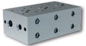
The bar manifold, as shown in Figure 4, supports all valves and contains all the passages for the entire hydraulic system.
A stackable modular plate assembly consists of two or more sub-plates connected to make a valve stack with an internal passage for a common pressure connection and an internal passage for a common tank connection. Each modular sub-plate unit supports only one valve and contains internal passages for the supported valve as well as flow-through provisions. It is normally connected to a series of similar modular blocks to make up a complete system.

Figure 4 | A bar manifold
There are two ways of manufacturing manifolds: That is: (1) A manifold can be made from a piece of steel, aluminium, or cast iron that can be drilled to provide the required flow passages. (2) A manifold can also be custom-made from several layers of steel sheets that have appropriate passages machined or milled through them. These sheets, along with solid metal end plates, are then stacked, and the whole stack is brazed. With this laminar design, the internal passages can be formed in contoured shapes and as large as possible. Therefore, in a manifold, any flow rate can be accommodated with minimum pressure drop.
The advantages of manifold systems include reduced costs of assembly and installation, decreased pressure drop, bare minimum leak points, and easy component interchangeability.
Joji Parambath
Author
References:
- Document on ‘Bar Manifold DO3 (Size 6) Parallel Circuit Normal Flow’ Finotek Machinery, www.finotek.com
- Document on ‘Port patterns NG 3 to NG 25’ WEBER-HYDRAULIK ValveTech GmbH, www.weber-hydraulik.com
- Document on ‘Serial Plates with Side Ports for ISO 4401-03 Valves’ Size 06 (D03) pmax 250 bar (3600 PSI)’, AGRO HYTOS, www.argo-hytos.com
- Document on ‘Subplates DO3 (Size 6) Bottom Ported’ Finotek Machinery, www.finotek.com
- Document on ‘Subplates SDO3, 5, 7 & 8’ HYVAIR, www.hyvair.com
- Documents on ‘DIRECTIONAL VALVE OPERATION: Directional Valve Features, Selection and Operating Recommendations’ and ‘Specifications: D03 Pattern Directional Control Valves’ DYNEX, www.dynexhydraulics.co.uk
- Interface ISO Size 03 to ISO 4401-03-02, Form A6 to DIN 24 340, NFPA T3.5.1 MR1 / ANSI B93.7M-D03’ Reference: 400-P-030501-EN-00, BUCHER Hydraulics, www.bucherhydraulics.com
- ISO 4401: Hydraulic fluid power — Four-port directional control valves —Mounting surfaces
- Technical information on ‘Overview mounting plates and mounting surfaces’, HAENCHEN, www.haenchen.de
Further Reading:
Industrial Hydraulics -Basic Level (In the English Units) by Joji Parambath

These books in paperback and Kindle eBook formats are available at Amazon marketplaces.
Are you looking for a course on Pneumatics and Hydraulics?
Please visit Fluidsys Training Centre Pvt. Ltd., Bangalore, India. https://fluidsys.in

Leave a Reply