
The 1950s marked a significant turning point in the design of hydraulic valves by introducing cartridge valves. This innovative approach paved the way for the evolution of cartridge valve technology, which now includes multifunction and integrated circuit features. Today, many cartridge valves are seamlessly incorporated into a single manifold block, demonstrating the far-reaching impact of this innovation. In recent years, further advancements have been made to enhance the technology’s performance, reducing leakage, complexity, and size while boosting reliability, efficiency, and cost-effectiveness.
Fundamental Concepts of Cartridge Valves
The basic cartridge valve, as shown in Figure 1, consists of an insert that slips into a cavity machined into a manifold. The cartridge valve system, as stated, consists of a mounting block (manifold) with appropriate flow passages and a control cover.
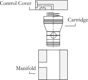
Figure 1 | The exploded view of the basic cartridge valve
Cartridge valves’ versatility is evident in their design. The cartridge is inserted into the manifold’s standardized cavity, and a control cover is placed over it and bolted to the manifold to retain it. This system allows for a wide range of control functions, with many standard covers available. Combining the cartridge with a suitable control cover can achieve the required control function. Moreover, cartridge valves are designed to meet specific international standards, enhancing adaptability.
Cartridge valves for directional and check functions are essentially hydraulically piloted check valves. They can also be designed for pressure and flow control functions. Each valve has only one control area in its spring chamber. However, there are logic valves, named active logic valves, each with a differential spool with two control areas. The following sections overview the cartridge valve circuits.
Symbols of Cartridge Valves
Figure 2 shows some control components used in cartridge valve systems and their variants. Figure 2(a) shows the symbol of an opening cartridge valve with two working areas, AA and AB. Figure 2(b) shows the symbol of an opening cartridge valve with only working areas AA (AB = 0). Figure 2(c) shows a closing cartridge valve. The valve remains open when a signal is applied to the pilot port.
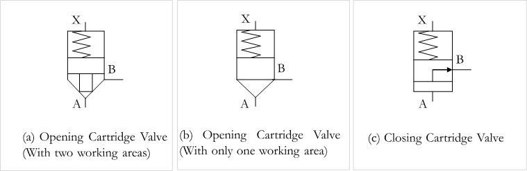
Figure 2 | Symbols of cartridge valves
Figure 3 shows the basic directional control cover used in cartridge valve systems and their variants.

Figure 3 | Symbols of basic covers of cartridge valves
A cartridge cover must operate reliably even in extreme load applications. It must be selected with a pressure rating suitable for the seal material used in the cover and the highest load expected in the associated system. The cover must also allow for maximum flows and lowest pressure drops. Control covers that integrate check, and shuttle valves and interfaces for subplate pilot valves must support a compact system design, even for complex functions.
Example 1 | A Circuit with an Opening Cartridge Valve Having Two Working Areas for A to B Directional Control
Figure 4 shows an opening cartridge valve’s basic circuit with two working areas, AA and AB. A pump is connected to port A of the valve, and a hydraulic motor is connected to port B. The pilot signal (X) is controlled externally using a 3/2-way valve.

Figure 4 | A circuit with an opening cartridge valve for A to B control
Figure 5 gives multiple positions of the circuit for port A to port B directional control.
If a signal is present at spring chamber port AP (the 3/2-way valve is actuated), the cartridge valve remains closed, and flow from port A to port B is blocked, as shown in Figure 5(a).
If the pilot signal is not present at port AP (the 3/2-way valve is released), flow from port A to port B is possible, as shown in Figure 5(b).
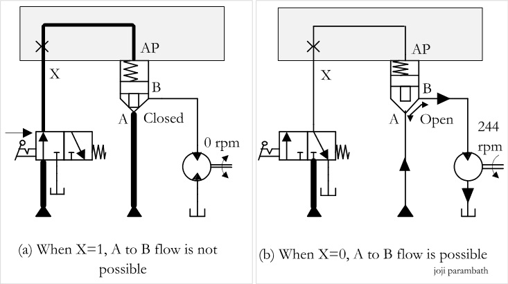
Figure 5 | Multiple positions of the circuit for A to B control
Example 2 | An Electro-hydraulic Circuit for the ON/OFF Control of a Hydraulic Motor Using a Cartridge Valve Employing External Piloting with a 3/2-way Solenoid Valve
Figure 6 shows an electro-hydraulic circuit for the ON/OFF control of a hydraulic motor using a cartridge valve with a control cover.

Figure 6 | An electro-hydraulic cartridge circuit employing external piloting for the control of a hydraulic motor
The cover has a mounting interface for a directional control pilot valve. A pump supplies the necessary fluid at the required pressure. A 3/2-way normally open (NO) type solenoid valve is used to pilot the cartridge valve externally. The control cover interfaces the 3/2-DC valve and the cartridge insert.
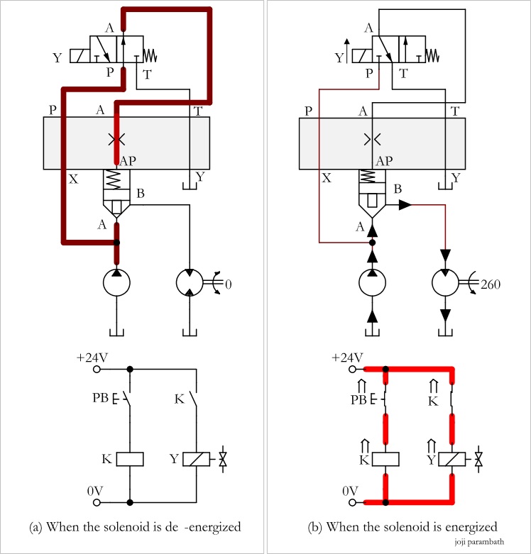
Figure 7 also gives multiple positions of the circuit. Figure 7(a) shows the electro-hydraulic circuit when pushbutton PB is released and the 3/2-way pilot valve is in its normal position. In this circuit position, the pump flow is directed to the cartridge valve’s pilot port AP through the 3/2-way valve, which closes tightly. As a result, the pump flow cannot pass through the cartridge valve, which prevents the hydraulic motor from running.
The pilot valve, with standard locations and patterns of ports and holes for mounting bolts and locating pins, can be directly installed on the cover with matching patterns of holes for ports, mounting bolts, and locating pins.
Figure 7(b) shows the circuit’s position when pushbutton PB is pressed, and the 3/2-way valve is actuated. In this circuit position, the pilot port pressure is relieved through the 3/2-way pilot valve to the tank, and the cartridge valve remains open when pressure is applied to port A. The pump flow can pass through the cartridge valve and drive the hydraulic motor. A properly sized and correctly placed orifice in the cartridge valve’s control cover allows for precise regulation of pressure and flow rate, which can increase efficiency and reliability.
Control Covers to Interface with 4-way Directional Control Valves
Cartridge valve control covers are available with mounting interfaces for single-solenoid or double-solenoid directional control valves. Figure 8 shows control covers for interfacing cartridge valve inserts with directional control valves. The control cover consists of many flow paths and ports, such as P, A, B, T, X, Z1, AP, Z2, and Y, as shown in the Figure. Port Z1 can be used for remote hydraulic control and should be blocked when not required. Port Y is usually the tank port.
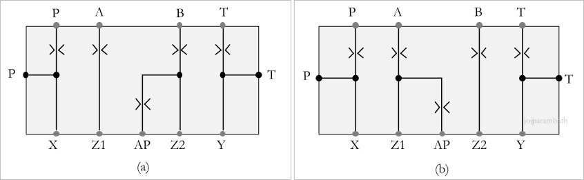
Figure 8 | Covers for cartridge valves as directional control interfaces
Figure 8(a) shows the control cover for connecting port B with pilot line AP internally, and Figure 8(b) shows the control cover for connecting port A with pilot line AP internally.
The following sections show that each control cover can be used with the cartridge insert and 4-way valve to configure a cartridge valve system. The internal pilot port X is connected internally to port B of the valve insert, and the pilot port Y is connected to the drain.
Example 3 | Directional Control of a Double-acting Hydraulic Cylinder Using Cartridge Valves in Bridge Circuit Arrangement
Develop an electrohydraulic circuit with four cartridge valves in a bridge circuit arrangement and four 3/2-way solenoid-operated directional control valves to realize the switching positions to control a double-acting cylinder’s forward and return strokes.
Solution
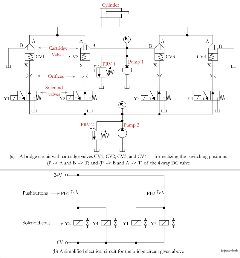
Figure 9 | The electro-hydraulic circuit with cartridge valves in bridge configuration and the electrical circuit
Figure 9 gives an electro-hydraulic circuit for directional control of the double-acting hydraulic cylinder using four cartridge valves, CV1, CV2, CV3, and CV4, in the bridge circuit arrangement. The cartridge valves’ pilot lines are controlled using the respective 3/2-way solenoid coils Y1, Y2, Y3, and Y4. The simplified electrical circuit for controlling the solenoid coils is given in Figure 9(b). Let us assume pump 1 supplies the main flow and pump 2 supplies the control flow.
A Cartridge Valve for a Pressure Control Function
Hydraulic pressure functions, such as pressure relief, unloading, and pressure-reducing, can be realized by combining a cartridge valve with suitable control covers. A cartridge insert in a pressure control valve typically includes a sleeve, a poppet with an area ratio 1:1, and a closing spring. It is retained in the manifold cavity by a control cover. The control cover contains a manually adjustable pilot valve and piloting connections. Suitable orifices can be added to the pilot circuit to match application requirements.
Pressure can be set manually or electronically. Manual adjusters include a micrometer with or without a key lock and a standard square-end screw with a hexagonal locknut. Pressure can be set electronically through a proportional valve. Many standards specify the mounting interfaces of cartridge valves for pressure control functions. ISO 7368 indicates the position of the orientation pin to be used with a main system relief valve. This feature ensures that no other valve function is installed where a system relief valve is required.
A Basic Cartridge Valve for the Pressure Relief Function
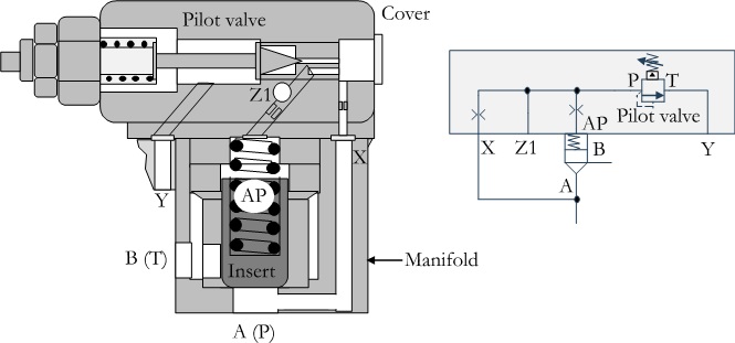
Figure 10 | A basic pressure relief valve in cartridge form
Figure 10 shows the cross-section and symbolic diagram of a cartridge-type pressure relief valve without an area differential. The valve can be integrated into or mounted onto the control cover. It also consists of orifices and ports X, Z1, AP, and Y, and a knob for setting the pressure. Pressure can be set over a wide range, typically from 3 to 350 bar (43 to 5000 psi).
Solution

Figure 11 | A cartridge valve circuit for the pressure relief function
Figure 11 shows the configuration of the cartridge valve with the 1:1 ratio insert, the control cover with the pressure relief valve, and the single solenoid pilot valve. The control cover consists of ports X, Z1, AP, Y, P, T, B, and A, and the insert consists of ports A and B.
The figure shows that the cartridge is vented when the solenoid is de-energized. When the solenoid is energized, the pressure at port A is limited to the setting of the pressure relief valve.
A Cartridge Valve for a Flow Control Function
Figure 6.1 shows a cartridge valve with an insert and a cover for flow control. The insert has a metering notch for the flow control function. The control cover has a stem, which limits the stroke of the insert and the flow. The flow can be adjusted by turning a knob, which moves the stem up or down to limit how far the poppet can open. When the pilot pressure is removed, the valve will open to a point where the stem is set.

Figure 12 | A control cover with an adjustable stroke limiter
Figure 13(a) shows an adjustable stroke limiter and directional function. The insert poppet opening’s adjustable limiting restricts flow in both directions (port A to port B and port B to port A). The external pilot signal is given through port X.
Figure 13(b) shows an adjustable stroke limiter and check function. Port X of the cover is connected to port B of the insert. The adjustable poppet lift limiter restricts flow from port A to port B, and the check function prevents flow from port B to port A.
Figure 13(c) shows an adjustable stroke limiter function and a pilot control through a 4/2-way single-solenoid valve.
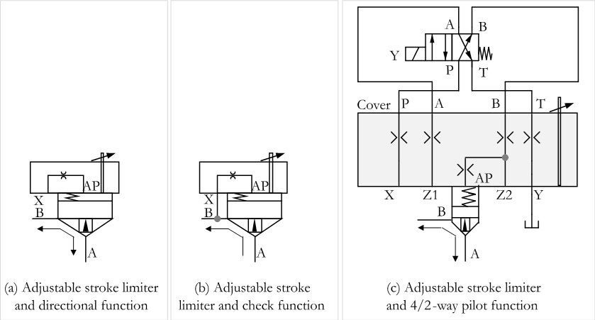
Figure 13 | Variants of adjustable stroke limiters
Actively Controllable Cartridge Valves
A cartridge valve logic assembly with only one control area in its spring chamber is regarded as a passive logic valve. In contrast, a logic assembly having a differential insert with two control areas is termed an active logic or dynamic valve. The dynamic insert extends above the manifold in an intermediate cover, creating an additional control area. The pilot pressure in the additional control area can keep the active logic valve open without pressure in port A or port B. The actively controlled logic assembly is designed to be compact, modular, and fast-acting.
2-way Cartridge valve, Actively Controllable
Figure 14 shows a 2-way, actively controllable cartridge valve, and an equivalent symbolic representation. It consists of a control spool (cartridge), an intermediate cover, and a control cover. The valve has two main ports, A and B, and two pilot ports, X and Y, on the intermediate cover. The pilot ports are used for remote control of the dynamic insert.
The spring chamber in the intermediate cover has a differential spool. The spool has areas A1, A2, and A4 in the opening direction and area A5 in the closing direction. The effective force acting on the spool determines the position and movement of the control spool. The pilot pressure in the control area (through Y) can keep the active logic open without pressure in ports A or B.
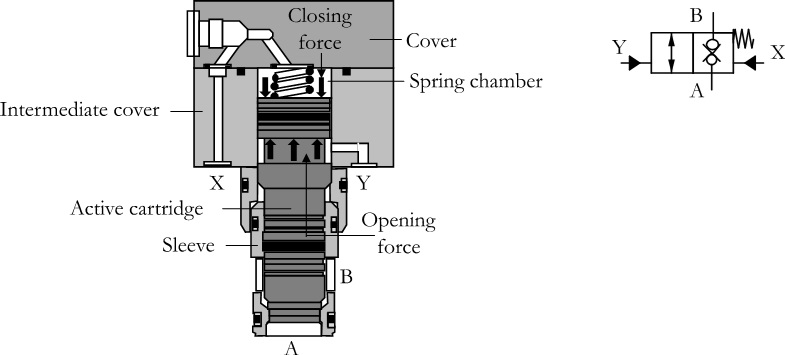
Figure 14 | 2-way cartridge valve, actively controllable
This control cover establishes connections with the pilot control valves and/or other hydraulic elements and thus integrates the different functions. All pilot and poppet seals create a tight fit at all ports to prevent leakage in either direction.
Type of Standard Inserts, Active Cartridge Valves
Active cartridge valves use various types of cones and sleeves. Three basic types are shown in Figure 15.
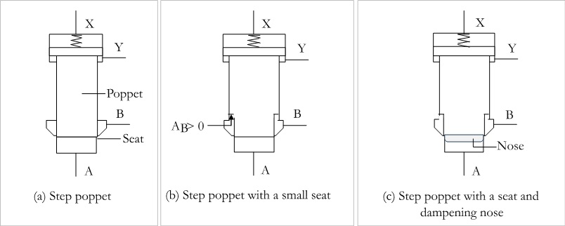
Figure 15 | Types of inserts of active cartridge valves
Example 5 | Control of an Accumulator Using an Active Cartridge Valve System
An active cartridge valve should control the fluid discharge of a hydraulic accumulator to a single-acting cylinder. A fixed-displacement pump supplies the necessary fluid to the system. A modular-type throttle check valve controls the cartridge’s opening speed. A metering orifice also controls the closing speed. Develop a control circuit.
Solution
Figure 16 shows a circuit controlling a hydraulic accumulator using an active cartridge valve. A constant-displacement pump supplies fluid to the system. The cartridge valve closes and opens the main flow path according to the pilot signals to its closing (X) and opening (Y) pilot ports. An orifice provided in the path of the pilot signal controls the speed of the cartridge valve’s closing, and a throttle check valve controls the cartridge valve’s opening speed.
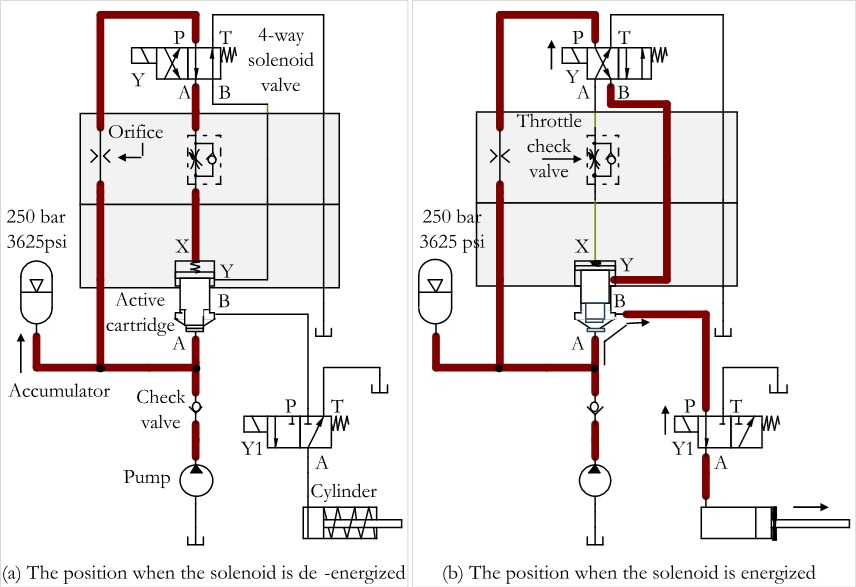
Figure 16 | Two positions of the circuit for the control of the accumulator using an active cartridge valve system
Figure 16(a) shows the position of the circuit when the solenoid of the 4-way pilot valve is de-energized. In this position, the pilot signal is directed to closing port X of the spring chamber through the orifice, and opening port Y of the spring chamber is relieved. Therefore, the cartridge valve is tightly closed. Figure 16(b) shows the position of the circuit when the solenoid of the 4-way pilot valve is energized. In this position, the pilot signal is directed to opening port Y of the spring chamber, and opening port Y of the spring chamber is relieved through the throttle valve. Therefore, the cartridge valve remains open.
Proportional Cartridge Valves and Circuits
A basic cartridge valve system consists of an insert installed in the cavity of a manifold, with appropriate flow passages and a control cover. The insert has several metering notches (orifices) to realize the flow control function.
Proportional Flow Control Cartridge Valves
A proportional flow control valve can be constructed like a switching 2-way, 3-way, or 4-way cartridge valve. The insert can be controlled using a proportional solenoid, which is, in turn, controlled by a current signal from an electronic controller. The required flow rate can be set using an input device like a potentiometer or joystick. When a current flows through the solenoid, the insert moves to open the control notches and proportionally increases the flow path cross-sectional area. The control produces a flow output through the valve proportional to the input current signal.

Figure 17 | Symbolic representations of proportional flow control valve
There are various cartridge-style flow control valves, such as in-line, 2-way, 3-way (priority), and 4-way flow control valves. A pressure-compensated flow control valve can provide a regulated flow proportional to the current input regardless of load or system pressure with the help of a pressure regulator. Figure 17 shows symbols of the following proportional cartridge-style flow control valves: (a) in-line pressure-compensated, (b) in-line priority pressure-compensated, (c) 2-way throttle, normally-closed, (d) 2-way throttle, normally-open, (e) 3-way throttle, and (f) 4-way throttle.
By
Joji Parambath
Author
Reference: Cartridge Valves by Joji Parambath
About the Book
Edition: Second | Year: 2024 | Platform: Kindle Direct Publishing | Formats: Paperback, Hardcover and Kindle eBook | No. of pages: 102 | Available: Amazon marketplaces
Book Content: This book provides an in-depth understanding of multi-function cartridge valves, including their concepts, configurations, and circuits for check, directional, flow, and pressure control functions. It also covers the active logic valves and proportional cartridge valves, as well as the constructional features of integrated manifolds. Additionally, it offers detailed information on cartridge valves’ characteristics, specifications, advantages, applications, and maintenance. The book is organized in an easy-to-understand manner, with many circuits given in multiple positions for quick comprehension. It is a great resource for anyone learning more about cartridge valves.
Table of Contents – Cartridge Valves by Joji Parambath
| Chapter | Description | Page No |
| 1 | Introduction to Cartridge Valves | 1 |
| 2 | Constructional Features and Circuits of Single-function Cartridge Valves | 5 |
| 3 | Constructional Features of Multi-function Cartridge Valves and Circuits for Check Function | 15 |
| 4 | Control Covers and Circuits for Directional Controls | 19 |
| 5 | Control Covers and Circuits for Pressure Controls | 32 |
| 6 | Control Covers and Circuits for Flow Controls | 43 |
| 7 | 3-way and 4-way Spool-type Cartridge Valves | 45 |
| 8 | Actively Controllable Cartridge Valves and Circuits | 48 |
| 9 | Proportional Cartridge Valves and Circuits | 55 |
| 10 | Constructional Features of Integrated Manifolds | 63 |
| 11 | Typical Characteristics and Specifications | 66 |
| 12 | Advantages of Cartridge Valve Systems | 70 |
| 13 | Applications of Cartridge Valve Systems | 72 |
| 14 | Installation and Maintenance of Cartridge Valve Systems | 74 |
| 15 | Objective Type Questions | 76 |
| 16 | Review Questions | 77 |
| Appendix 1 | Symbols of Cartridge Inserts | 81 |
| Appendix 2 | Symbols of Cartridge Covers | 82 |
| Appendix 3 | Mounting Configurations of 4-port Hydraulic Directional Control Valves | 84 |
Are you looking for a course on Pneumatics and Hydraulics?
Please visit Fluidsys Training Centre Pvt. Ltd., Bangalore, India. https://fluidsys.in